Understanding Photoelectric Sensor Fiber Optic Cables
Photoelectric sensors utilize fiber optic cables to transmit light signals between the emitter and receiver units. These cables are composed of a core, cladding, and protective jacket, designed to guide light efficiently with minimal loss. The core, typically made of glass or plastic, carries the light beam, while the cladding reflects it inward to prevent signal dispersion. Fiber optic cables enable sensors to operate in harsh environments by separating the electronic components from the sensing point, protecting them from dust, moisture, and extreme temperatures. Selecting the appropriate cable type—such as single-mode for long distances or multi-mode for shorter ranges—is crucial for optimal performance. Engineers must consider factors like bending radius and attenuation to ensure reliable signal transmission in industrial applications.
Components of a Fiber Optic Wiring System
A standard photoelectric sensor fiber optic wiring system includes several key components: the sensor amplifier, fiber optic cables, connectors, and mounting accessories. The sensor amplifier processes the light signal, converting it into an electrical output for control systems. Connectors, such as SMA or ST types, secure the cables to the amplifier and sensing heads, ensuring alignment for efficient light coupling. Mounting brackets and protective sleeves help position the cables safely, avoiding sharp bends or physical damage. In complex setups, splitters or couplers may integrate multiple fibers for multi-point sensing. Each component must be compatible with the sensor's specifications, including wavelength (e.g., 660 nm for visible red light) and cable diameter, to maintain system integrity and accuracy.
Step-by-Step Wiring Diagram Interpretation
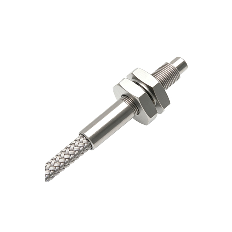
Interpreting a wiring diagram for photoelectric sensor fiber optics involves analyzing symbols and connections. Typically, diagrams depict the amplifier unit with terminals for power supply (e.g., 12-24 VDC), output signals (NPN/PNP), and fiber optic ports. The emitter and receiver fibers are shown as lines connecting to sensing heads, often labeled with icons for through-beam, retroreflective, or diffuse modes. For example, in a through-beam setup, the diagram illustrates separate fibers aligned opposite each other, while a diffuse diagram shows a single fiber for both emission and reception. Grounding symbols and shield connections indicate noise protection measures. Engineers should follow color codes—like black for output and blue for common—to wire correctly, referencing manufacturer manuals for specific pin configurations and safety guidelines.
Installation Best Practices and Tips
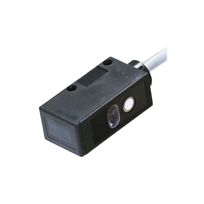
Proper installation ensures longevity and accuracy in fiber optic sensor systems. Begin by powering off all equipment to prevent electrical hazards. Route cables away from high-voltage lines or motors to minimize electromagnetic interference. Use cable ties or conduits to secure fibers, maintaining a bend radius greater than 10 times the cable diameter to avoid signal loss. Clean connectors with lint-free wipes and isopropyl alcohol before mating, as dust can obstruct light paths. When connecting to amplifiers, tighten connectors firmly but avoid over-torquing to prevent damage. Test the system with a target object to verify sensing range and adjust amplifier sensitivity settings as needed. Regular inspections for wear or contamination help prevent downtime in automation processes.
Common Issues and Troubleshooting Methods
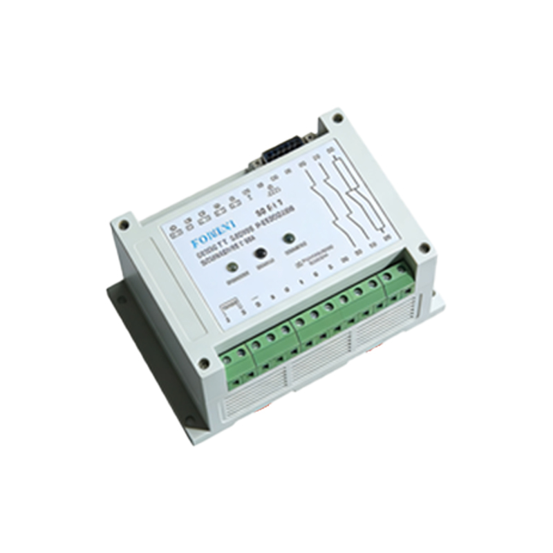
Despite careful installation, issues like signal dropout or false triggers may arise. Start troubleshooting by checking the power supply voltage with a multimeter to ensure it meets sensor requirements. Inspect fiber optic cables for cracks, kinks, or contamination, replacing damaged sections if necessary. Use an optical power meter to measure light intensity at the receiver end; low readings may indicate misalignment or degraded fibers. Verify that sensing heads are properly aligned in through-beam applications, and clean lenses regularly. If interference is suspected, relocate cables or add ferrite cores. Consult the amplifier's indicator LEDs—often showing green for normal operation or red for faults—to diagnose problems quickly, referring to error codes in technical documentation.
Applications in Industrial Automation
Photoelectric sensors with fiber optics are vital in diverse industrial settings due to their versatility and durability. In packaging lines, they detect transparent bottles or labels by adjusting to subtle light changes. Automotive assembly uses them for precision part positioning, leveraging small fiber heads to fit tight spaces. Food processing industries rely on these sensors for hygiene, as fibers can withstand washdowns without corrosion. Additionally, in high-temperature environments like metalworking, fibers isolate electronics from heat sources. Advanced setups incorporate programmable amplifiers for teach-in functions, allowing adaptive sensing in dynamic processes. By integrating with PLCs via IO-Link or Ethernet protocols, these sensors enable real-time monitoring and data logging for smart manufacturing initiatives.
Future Trends and Innovations
The evolution of photoelectric sensor fiber optics focuses on enhanced connectivity and miniaturization. Emerging trends include the adoption of plastic optical fibers (POF) for cost-effective, flexible solutions in short-range applications. Smart sensors with embedded diagnostics can predict maintenance needs by analyzing signal trends over time. Integration with IIoT platforms allows remote configuration and analytics, improving efficiency in distributed systems. Innovations in materials, such as bend-insensitive fibers, expand installation possibilities in constrained spaces. Furthermore, developments in wavelength-division multiplexing enable multiple sensors to share a single fiber, reducing wiring complexity. As industries advance toward Industry 4.0, these technologies will drive greater automation reliability and energy savings.