Understanding the 8plus Proximity Sensor System
The 8plus series of proximity sensors represents a significant advancement in non-contact detection technology, widely implemented in automated manufacturing, packaging, and material handling systems. These inductive sensors are designed for reliability in harsh industrial environments, detecting the presence of metallic objects without physical contact. The core operating principle relies on generating an electromagnetic field from an oscillator circuit. When a metallic target enters this field, eddy currents are induced, causing a change in the oscillation amplitude. This change is detected by a threshold circuit, which subsequently switches the output state. The 8plus models often incorporate advanced features like teach-in functionality, short-circuit and overload protection, and robust housing with high ingress protection ratings. A comprehensive understanding of this system—encompassing power supply requirements (typically 10-30V DC), output types (PNP/NPN, NO/NC), and sensing ranges—is fundamental before initiating any diagnostic procedure. Incorrect installation or configuration remains a primary, yet often overlooked, precursor to perceived sensor failure.
Common Symptoms of Proximity Sensor Failure
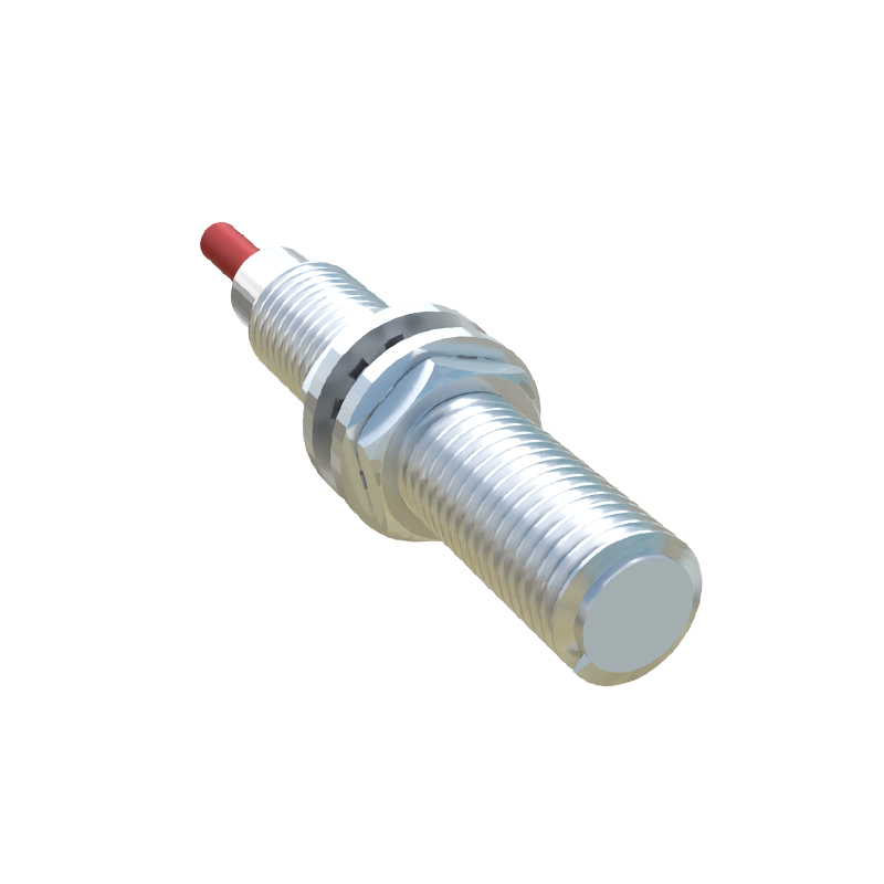
Identifying a malfunctioning 8plus sensor requires careful observation of system behavior. The most frequent symptom is intermittent or complete loss of detection. The machine may fail to register a part's presence, causing process stoppages or faulty sequencing. Conversely, a sensor may exhibit "sticking," where the output remains constantly active or inactive regardless of target position. Erratic behavior, such as triggering at inconsistent distances or being influenced by non-target metals (adjacent machinery, brackets), also indicates issues. Physically, visible damage to the sensor housing or cable is a clear sign. From an electrical diagnostic perspective, an unstable or absent output signal when measured with a multimeter or oscilloscope is a definitive indicator. It is critical to differentiate between a true sensor fault and failures in interconnected components like PLC input modules, wiring, or the power supply unit. A systematic approach to symptom analysis prevents unnecessary sensor replacement.
Step-by-Step Electrical Diagnosis Procedure
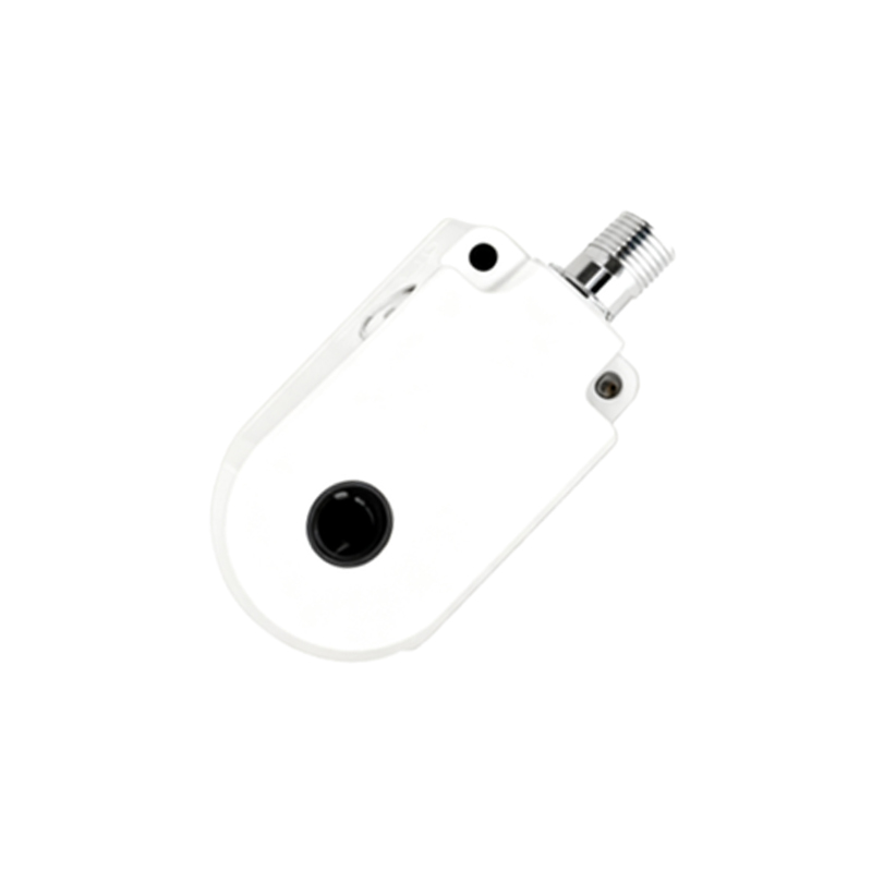
A methodical diagnostic approach is essential for efficient troubleshooting. Begin by verifying the power supply. Using a calibrated digital multimeter, measure the voltage across the sensor's supply terminals (typically brown/+ and blue/- wires). Ensure it is stable and within the specified range (e.g., 24V DC ±10%). Voltage drops or excessive ripple can cause malfunction. Next, inspect the output signal. For a DC 3-wire sensor, with power applied and a target absent, measure the voltage between the black (output) wire and the blue (common) wire. An NPN (sinking) output should read near supply voltage when off; a PNP (sourcing) output should read near 0V. Introduce a target to the sensing face. The voltage should switch states. Use an oscilloscope if available to check for signal integrity and switching speed. Always consult the specific 8plus datasheet for wiring diagrams and nominal values. Simultaneously, perform a visual and mechanical inspection for misalignment, accumulated metallic debris on the sensing face, and damage to the cable or connector.
Environmental and Interference Factors
Sensor performance is heavily influenced by the installation environment. Electrical noise from variable frequency drives (VFDs), welding equipment, or large motors can induce false triggering. Ensure sensor cables are routed away from power lines, preferably in separate conduits, and use shielded cables with proper grounding at the controller end only. Mutual interference between closely mounted sensors can occur; maintain a minimum distance as specified in the manual (often 2-3 times the sensor diameter). Environmental factors such as extreme temperatures, corrosive chemicals, or high-pressure washdown can degrade sensor components over time, even if the housing is rated for it. Check for condensation inside the housing. Furthermore, ensure the target material, size, and approach angle meet the sensor's specifications. An 8plus sensor calibrated for mild steel will have a reduced sensing range for stainless steel or aluminum, which may be mistaken for a fault.
Advanced Troubleshooting and Replacement Guidelines
If basic electrical checks are inconclusive, advanced troubleshooting may involve isolating the sensor. Temporarily connect the sensor to a known-good, independent power supply and load (like a pilot light) to eliminate external circuit issues. Some 8plus models have an LED status indicator; a solid or flashing LED can provide fault codes (refer to the manual). For programmable models, a reset to factory defaults or a re-teach of the sensing distance might resolve drift issues. When replacement is necessary, ensure an exact match of key parameters: operating voltage, output type (PNP/NPN), output function (NO/NC), housing size, and sensing range. Note the electrical