Building a laser beam sensor at home is an engaging project that combines basic electronics, optics, and practical problem-solving. This guide walks through creating a simple yet effective laser-based detection system, commonly used for security alarms, object counters, or interactive displays. The core principle involves aligning a laser diode emitter with a photoresistor or phototransistor receiver; when the beam is interrupted, the circuit triggers a response like a buzzer or LED.
First, gather the essential components. You will need a low-power laser module (typically 5mW red laser, Class IIIa), a light-dependent resistor (LDR) or a phototransistor as the receiver, a breadboard, jumper wires, resistors (e.g., 10kΩ), a transistor (like BC547) or an operational amplifier (LM358), a buzzer or LED for output, and a power source such as a 9V battery with a regulator. Always prioritize safety: avoid pointing the laser at eyes or reflective surfaces, and use appropriate eye protection if needed.
Start by constructing the emitter circuit. Connect the laser module to the power supply, ensuring correct polarity. Most modules require a 3V to 5V DC input; a current-limiting resistor may be integrated. For stability, mount the laser on a stand or holder, allowing precise directional adjustment. A simple switch can be added to control power.
Next, build the receiver circuit. Place the LDR on the breadboard in a voltage divider configuration with a fixed resistor (e.g., 10kΩ). Connect the divider’s midpoint to the base of an NPN transistor or the non-inverting input of an op-amp. When the laser beam strikes the LDR, its resistance drops, increasing the voltage at the midpoint. This change activates the transistor or op-amp, which drives the output device. For better sensitivity in ambient light, use a phototransistor with a focusing tube or enclosure to block stray light. Calibration is key: adjust the fixed resistor value or add a potentiometer to set the trigger threshold.
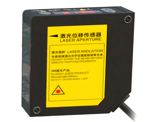
Alignment is the most critical step. Position the emitter and receiver facing each other on a stable surface. Use a dark environment initially to see the beam spot clearly. Fine-tune their positions until the receiver detects the maximum light intensity, indicated by a multimeter reading or the output staying inactive. Secure the components with adhesive or mounts to prevent drift.
To enhance functionality, integrate a timer circuit (like a 555 IC) for a pulsed beam, reducing interference from ambient light. Adding a relay module allows controlling higher-power devices. For wireless alerts, connect an Arduino or ESP8266 to send notifications via Wi-Fi.
Testing involves interrupting the beam with an object; the buzzer should sound or LED light up immediately. Troubleshoot issues like false triggers by checking for ambient light leaks, power fluctuations, or misalignment. Regular maintenance ensures long-term reliability.
This project offers a hands-on introduction to optoelectronics and circuit design. With careful assembly and calibration, a DIY laser beam sensor can be a reliable, cost-effective solution for various applications, sparking further exploration into advanced sensor systems.