Understanding Photoelectric Sensor Voltage Fundamentals
Before initiating any measurement, it is crucial to understand the voltage specifications of your photoelectric sensor. Most industrial photoelectric sensors operate on DC voltages, commonly 10-30 VDC, or sometimes on AC voltages like 90-250 VAC. The sensor's datasheet is the primary source of truth. It will specify the operating voltage range, the nominal voltage, and the allowable ripple or tolerance. A sensor designed for 12-24 VDC, for instance, should not be subjected to a constant 30 VDC, as this can lead to premature failure or erratic operation. Additionally, identify whether the sensor is a 2-wire, 3-wire, or 4-wire device. This directly impacts how you connect your measuring equipment. A 3-wire sensor, the most common type, will have separate wires for power supply positive (brown), power supply negative/0V (blue), and the output signal (black or another color). Knowing these basics prevents misconnection and potential damage.
Essential Tools and Safety Precautions
Gather the correct tools: a digital multimeter (DMM) with DC and AC voltage measurement capabilities is essential. For diagnosing noise or ripple, an oscilloscope is highly recommended. Ensure you have appropriate test leads with fine probes or alligator clips for secure connections. Safety is paramount. Always de-energize the circuit before making or breaking connections to the sensor's wiring, unless you are taking a live voltage reading at designated test points. If working on live circuits, wear appropriate personal protective equipment (PPE). Verify the multimeter's settings are correct for the expected voltage type (AC/DC) and range before connecting. A common mistake is having the probes in the current measurement jacks while trying to measure voltage, which can blow the meter's fuse or cause damage.
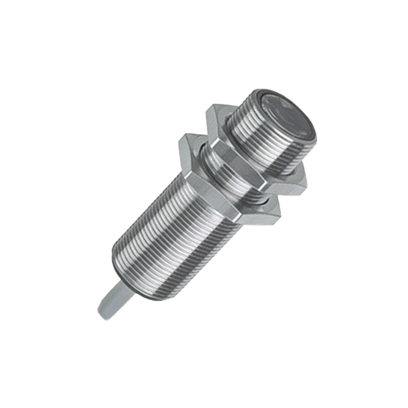
Measuring Supply Voltage at the Sensor Terminals
This is the first and most critical diagnostic step. It confirms whether the sensor is receiving power within its specified range. For a 3-wire DC sensor, power on the system. Set your DMM to DC voltage on a range higher than the expected voltage (e.g., 200 VDC scale for a 24V system). Connect the black (common) probe to the sensor's blue wire (0V/negative) or a known good ground point. Connect the red (positive) probe to the sensor's brown wire (V+). The reading should be stable and within the sensor's operating range (e.g., 23.8 to 24.2 VDC for a nominal 24V system). A reading of zero indicates a broken connection, blown fuse, or faulty power supply. A reading significantly low suggests a overloaded circuit or failing power supply. Repeat this for AC sensors using the AC voltage setting.
Measuring Output Signal Voltage
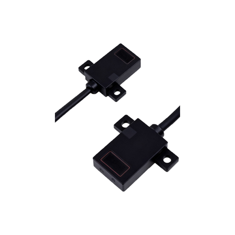
The output voltage indicates the sensor's state. For a DC sensor with a transistor output (NPN sinking or PNP sourcing), the output is a switched DC voltage relative to the 0V line. With the sensor powered, set the DMM to DC voltage. Keep the black probe on the 0V (blue) wire. Touch the red probe to the output wire (often black). Observe the reading while triggering the sensor. For a PNP (sourcing) sensor, the output should read close to the supply voltage (e.g., 24V) when active (light received for a through-beam, object present for a diffuse), and near 0V when inactive. For an NPN (sinking) sensor, the logic is inverted: near 0V when active, and floating or at a high impedance when inactive (though you may read a small induced voltage). An analog output sensor will provide a varying voltage (e.g., 0-10V) proportional to the measured distance or light intensity.
Diagnosing Voltage Drops and Electrical Noise
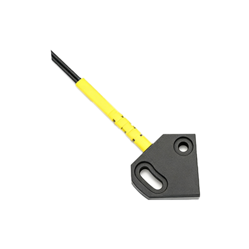
A correct supply voltage at the power source but a low voltage at the sensor indicates a voltage drop in the wiring. Perform a voltage drop test: measure the voltage between the power supply's positive terminal and the sensor's brown wire while the sensor is operating. A significant reading (more than 0.5V) points to high resistance in the wire, a loose connection, or a corroded terminal. Electrical noise can cause erratic sensor behavior even with correct average voltage. Use an oscilloscope to observe the supply and output lines. Look for high-frequency spikes, ripple, or sag. Noise on the supply line often requires the addition of a filter or a dedicated sensor power supply. Ensure proper shielding of cables and separation from high-current AC lines. Ground loops can also introduce noise; ensure a single-point ground reference.
Interpreting Results and Troubleshooting Common Issues
Correlate your voltage measurements with the sensor's expected behavior. A good supply voltage but no change in output voltage suggests a sensor fault, misalignment, a dirty lens, or an issue with the target (wrong color, size, or material). If the output voltage changes but the connected PLC or controller does not register it, the issue may be with the input circuit of the controller (e.g., wrong input type, damaged channel) or wiring to it. Consistently low output voltage swing (e.g., only switching between 5V and 0V on a 24V system) can indicate a failing output transistor or an excessive load. Always cross-check with the manufacturer's documentation, as some sensors have diagnostic LEDs that blink specific codes for faults, which, combined with voltage readings, provide a complete diagnostic picture.