Introduction to the MN15-M30G Proximity Sensor
The MN15-M30G represents a specific class of industrial proximity sensors, designed for reliable non-contact detection in demanding automation environments. As a 3-wire DC inductive sensor, it is engineered to detect the presence of metallic objects without physical contact, thereby eliminating mechanical wear and enabling high-speed operation. The "MN" designation typically refers to a cylindrical housing, with "15" and "30" indicating common thread sizes (M15 and M30), and "G" often specifying a particular sensing distance or output configuration. These sensors are fundamental components in modern manufacturing, robotics, and material handling systems, providing critical feedback for process control and machine safety.
Core Operating Principle and 3-Wire Configuration
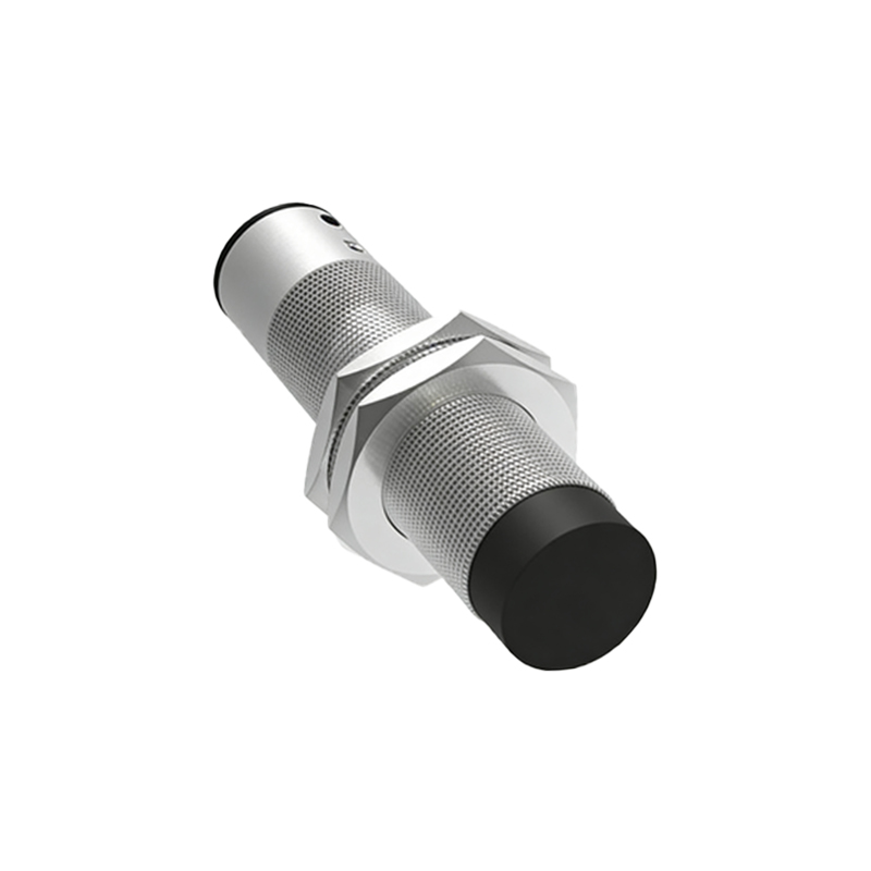
At its heart, the MN15-M30G operates on the principle of electromagnetic induction. An internal oscillator generates a high-frequency electromagnetic field at the active face of the sensor. When a metallic target enters this field, eddy currents are induced in the target, causing a change in the oscillator's amplitude. This change is detected by the sensor's circuitry, which then triggers a solid-state switching output. The 3-wire DC configuration is industry-standard, comprising three distinct wires: brown for positive supply voltage (typically +V DC, e.g., 10-30V DC), blue for the common negative or 0V, and black for the switched output signal. This setup allows for either NPN (sinking) or PNP (sourcing) output types, with the black wire providing the signal path to the load (like a PLC input).
Key Technical Specifications and Performance Data
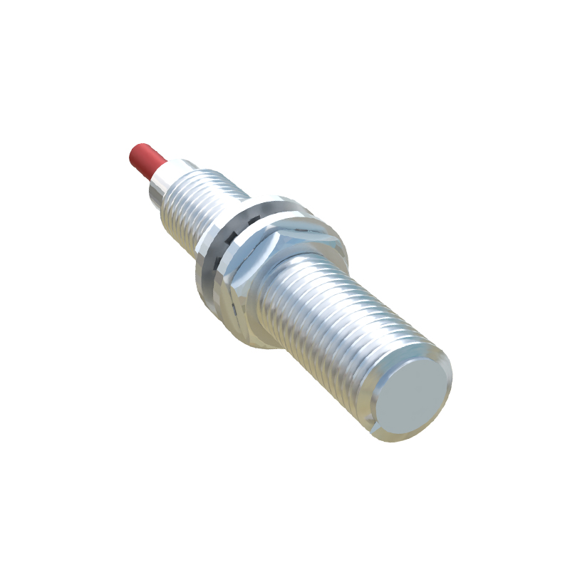
Understanding the datasheet parameters is crucial for correct application. Key specifications for the MN15-M30G series include sensing distance, which is rated (e.g., 2mm for M15, 8mm for M30) for standard mild steel. Factors like target material, size, and shape can affect this distance. The operating voltage range is usually 10-30V DC, with low current consumption. The output is a solid-state switch, capable of driving loads up to a specified current (e.g., 200mA). Other vital parameters are switching frequency (response speed), hysteresis (to prevent chatter), protection class (IP67/IP69K for resistance to dust and water), temperature range, and short-circuit/overload protection. Always consult the manufacturer's specific datasheet for the exact model variant.
Wiring Diagrams and Connection Guidelines
Correct wiring is paramount for safe and reliable operation. For a standard 3-wire PNP (sourcing) MN15-M30G sensor: connect the brown wire to the positive DC supply terminal, the blue wire to the negative/0V terminal, and the black output wire to the positive side of the load (e.g., a PLC digital input module). The other side of the load is then connected to 0V. For an NPN (sinking) version, the black wire is connected to the load, and the other side of the load is connected to +V. It is essential to ensure proper grounding and shielding in electrically noisy environments. Always implement fuse protection in the supply line and verify polarity before powering the circuit to prevent damage.
Application Scenarios in Industrial Automation
The robustness and reliability of the MN15-M30G make it suitable for diverse applications. Common uses include position detection of machine parts (e.g., cylinder end positions), counting objects on a conveyor belt, monitoring the presence of tools in a CNC magazine, detecting the end of a material roll, and ensuring safety interlocking by confirming a guard is closed. The M30 version, with its longer sensing range and sturdy build, is often used in heavy machinery and outdoor applications, while the M15 variant is ideal for space-constrained installations.
Installation Best Practices and Environmental Considerations
Proper installation extends sensor life and ensures accuracy. Mount the sensor securely using its threaded barrel, ensuring it is flush and aligned correctly with the target path. Maintain the specified nominal sensing distance (Sn) and account for any reduction factors for non-ferrous metals. Avoid mounting multiple sensors in close proximity to prevent mutual interference; maintain a minimum spacing as per guidelines. Consider environmental factors such as extreme temperatures, chemical exposure, and heavy vibration, selecting models with appropriate housing materials (e.g., stainless steel) and ratings. Regular maintenance involves cleaning the sensing face of debris and checking for physical damage.
Troubleshooting Common Operational Issues
Systematic troubleshooting can quickly resolve most sensor problems. If the sensor fails to detect, verify power supply voltage and polarity