Introduction to Photoelectric Speed Measurement
Photoelectric sensors have become a cornerstone technology in industrial automation for non-contact speed measurement. Their principle of operation is elegantly simple yet highly effective, relying on the interruption or reflection of a light beam to detect the presence or movement of an object. In rotational speed measurement applications, these sensors offer distinct advantages over mechanical tachometers, including minimal wear, high accuracy, and the ability to measure without physical contact, which is crucial for delicate or high-speed machinery. This experiment outlines a standard procedure for utilizing a through-beam photoelectric sensor to measure the rotational speed of a motor shaft, providing a hands-on understanding of the setup, signal processing, and data interpretation involved in this common industrial task.
Required Equipment and Components
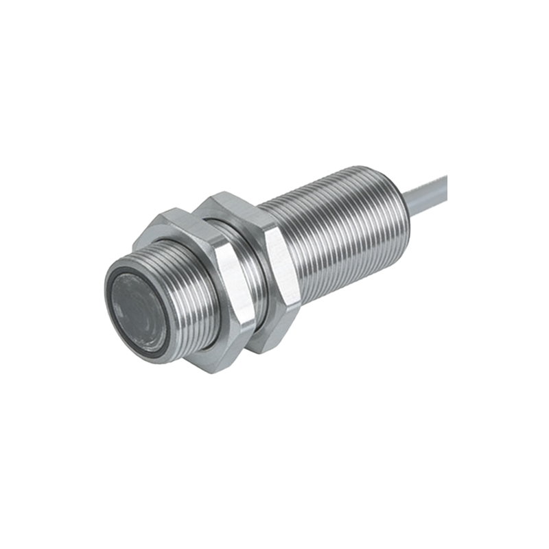
To conduct this experiment, a specific set of equipment is necessary. The core component is a through-beam (or opposed) photoelectric sensor pair, consisting of a separate emitter and receiver. You will need a variable-speed DC motor or a motor with an attached encoder disk for testing purposes. The disk should have clearly defined, evenly spaced slots or reflective marks. Essential electronic equipment includes a stable DC power supply for the sensor (typically 12-24V DC), an oscilloscope for visualizing the sensor's output signal, and a frequency counter or a microcontroller (like an Arduino or PLC) capable of measuring pulse frequency. Additionally, basic tools for mounting, such as a breadboard, jumper wires, and mechanical fixtures to align the sensor with the rotating disk, are required. Always prioritize safety by ensuring all electrical connections are secure before powering the system.
Experimental Setup and Sensor Alignment
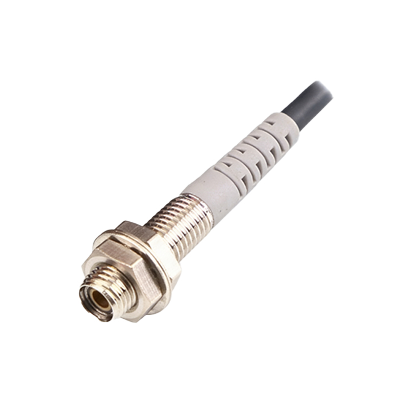
Proper physical setup is critical for reliable data acquisition. Begin by securely mounting the motor and its slotted disk. The photoelectric sensor pair must be positioned so that the disk rotates through the gap between the emitter and receiver. The emitter projects a focused beam of light (often infrared) towards the receiver. As each slot on the disk passes through the beam, light reaches the receiver, generating a high signal. When the opaque section of the disk interrupts the beam, the signal goes low. Precise alignment is paramount; even slight misalignment can cause signal dropout. Use mounting brackets to ensure the sensor pair is perfectly opposed and that the disk rotates cleanly through the beam path without physical contact. Connect the sensor's output wire (usually the collector of an open-collector NPN transistor) to your measurement device.
Signal Analysis and Waveform Observation
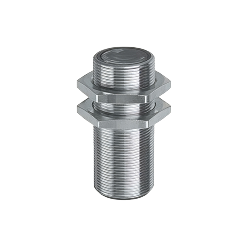
Once the system is powered, use the oscilloscope to observe the sensor's digital output signal. With the motor rotating, you should observe a clear, square-wave pulse train on the oscilloscope display. Each complete cycle (one high pulse and one low pulse) corresponds to the passage of one slot and one opaque section. Key parameters to examine are the signal amplitude (which should match the sensor's specified voltage, e.g., 5V or 24V), the rise and fall times (which should be sharp for accurate detection), and the absence of noise or jitter. The stability of this waveform directly impacts measurement accuracy. Adjust the sensor's positioning if the signal is unstable or the amplitude is reduced. The oscilloscope will also allow you to directly measure the period (T) of one pulse cycle, which is the inverse of the frequency (f = 1/T).
Calculating Rotational Speed from Frequency
The fundamental relationship for calculating rotational speed (N) from the sensor output frequency (f) is straightforward. First, determine the number of pulses per revolution (P). This is equal to the number of slots or reflective marks on the disk. The frequency (f) measured in Hertz (Hz, or pulses per second) is the rate at which pulses are generated. The rotational speed in Revolutions Per Minute (RPM) is then calculated using the formula: N (RPM) = [f (Hz) * 60 seconds] / P. For example, if your disk has 10 slots (P=10) and your frequency counter reads 250 Hz, the rotational speed is (250 * 60) / 10 = 1500 RPM. This calculation can be performed manually, programmed into a microcontroller, or displayed directly by a digital tachometer module that processes the pulse input.
Error Sources and Calibration Considerations
Several potential sources of error can affect the measurement's precision and accuracy. Mechanical errors include disk eccentricity (the disk not being centered on the shaft), wobble, or uneven slot spacing. Electrical errors may stem from sensor response time limitations, especially at very high speeds, or electrical noise inducing false pulses. Ambient light interference can sometimes affect certain photoelectric sensors. Calibration is essential for high-precision applications. This can involve comparing the sensor reading against a known reference, such as a calibrated laser tachometer. Adjustments might be needed in the software calculation (e.g., a correction factor) or in the physical setup to minimize systematic error. Understanding these factors ensures the reported data is reliable for process control or diagnostic purposes.
Practical Applications and Conclusion
The practical applications of photoelectric speed measurement are vast across the electrical and automation industries. It is used for monitoring conveyor belt speeds, motor and turbine RPM in manufacturing, fan control in HVAC systems, and as a feedback mechanism in closed-loop motor drives. This experiment provides a foundational, hands-on methodology that engineers can adapt and scale for real-world scenarios. Mastery of this technique involves not just the calculation, but also the critical skills of sensor selection, robust mechanical integration, signal integrity verification, and error analysis. By following this guide, engineers can confidently implement and troubleshoot photoelectric speed sensing systems, ensuring accurate and reliable rotational data for maintenance, control, and optimization of industrial equipment.