Understanding the Photoelectric Sensor Speed Output
The speed output from a photoelectric sensor is a critical signal in modern industrial automation and process control. At its core, this functionality transforms the detection of a moving object—often via an interrupted light beam—into a quantifiable frequency or pulse train directly proportional to the object's rotational or linear speed. Unlike a simple on/off detection signal, the speed output provides dynamic, real-time data about motion. This is typically achieved through an encoder-like mechanism integrated within the sensor or its associated circuitry. As a marked object, such as a reflective patch on a shaft or a tooth on a gear, passes through the sensor's field, it generates a series of electrical pulses. The frequency of these pulses, measured in Hertz (Hz) or pulses per second (PPS), is the fundamental speed output. Advanced sensors may directly convert this frequency into standardized analog signals (e.g., 4-20 mA, 0-10 V) or digital communication protocols (e.g., IO-Link, PROFINET), representing speed as a scaled value for direct use by programmable logic controllers (PLCs) and other control systems.
Core Operating Principles and Technologies
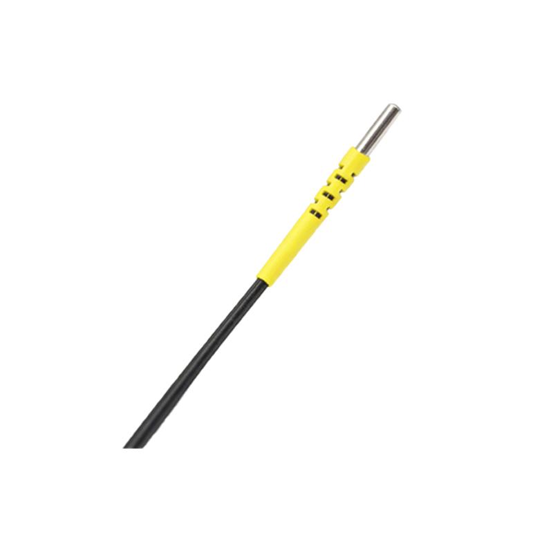
The generation of a reliable speed signal hinges on the sensor's internal technology. The most common method involves a modulated infrared LED light source and a phototransistor receiver. When the beam is uninterrupted, the receiver's state is stable. A moving target with alternating reflective and non-reflective sections causes the received light intensity to fluctuate. This analog fluctuation is conditioned, amplified, and converted into a clean, square-wave digital pulse by a Schmitt trigger circuit within the sensor. The key specification here is the sensor's maximum response frequency or switching frequency, which dictates the highest rotational speed it can accurately measure. For high-speed applications, sensors with faster response times (in microseconds) and higher switching frequencies (often in the kHz range) are essential. Furthermore, background suppression technology and precise optical design are crucial to eliminate false triggers from ambient light or environmental contaminants, ensuring signal integrity for accurate speed calculation.
Key Applications in Industrial Systems
Photoelectric sensors with speed output are indispensable across numerous industries. In conveyor systems, they monitor belt speed for synchronization, slip detection, and throughput calculation. On rotating machinery like motors, pumps, and fans, they serve as non-contact tachometers, providing vital data for condition monitoring, overspeed protection, and closed-loop speed control. Within packaging machinery, they ensure precise timing by measuring the speed of film feeds or product flow. In the automotive sector, they are used on assembly lines to monitor the speed of engines on test stands or the rotation of wheels for alignment. The textile industry employs them to control the speed of spinning frames and looms. The non-contact nature of photoelectric sensing makes it ideal for applications where physical wear from contact tachometers is unacceptable or where the target is inaccessible.

Output Signal Types and Interface Considerations
Selecting the correct output type is paramount for system integration. The most basic form is an NPN or PNP open-collector transistor output that provides a raw pulse train. This signal must be interpreted by a high-speed counter input on a PLC to calculate RPM or FPM (Feet Per Minute). For direct analog integration, many sensors offer a proportional voltage or current output, where, for example, 0 V represents 0 RPM and 10 V represents the maximum measurable speed. This simplifies wiring and PLC programming. Increasingly, smart sensors with IO-Link capability are becoming the standard. IO-Link not only transmits the processed speed value digitally but also allows for remote configuration, diagnostics, and parameterization of the sensor, such as setting scaling factors or filtering parameters, greatly enhancing system flexibility and maintenance.
Critical Selection Criteria for Optimal Performance
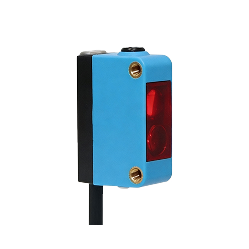
Choosing the right sensor requires careful analysis of several parameters. First, define the required measuring range (minimum and maximum speeds) and resolution. The sensor's switching frequency must exceed the maximum pulse frequency generated by the target. Consider the sensing distance and the size of the target features; smaller features or greater distances may require sensors with a focused beam or higher precision. The environment is critical: sensors with robust housings (IP67/IP69K ratings) are needed for washdown or dusty areas. For detecting difficult surfaces (e.g., shiny metal), a polarized retro-reflective or diffuse sensor with background suppression might be necessary. Finally, evaluate the required output signal (discrete, analog, or digital bus) and the electrical supply voltage (12-24 VDC is common) to ensure compatibility with the existing control architecture.
Installation, Alignment, and Maintenance Best Practices
Proper installation is key to signal accuracy. The sensor must be securely mounted to prevent vibration-induced errors. Precise alignment between the sensor, the light beam, and the target's marks is crucial; misalignment can cause missed counts or erratic signals. For through-beam sensors, ensuring the emitter and receiver are perfectly opposite is vital. For reflective models, the correct angle and distance must be maintained. Regular maintenance involves keeping the lens clean from dust, oil, or debris that can attenuate the light signal. Periodically verifying the output signal with an oscilloscope or a PLC monitoring tool can confirm that the pulse waveform remains clean and consistent, preventing downtime due to gradual performance degradation.