Introduction to Through-Beam Sensor Assembly
Assembling a through-beam photoelectric sensor correctly is crucial for ensuring reliable operation in industrial automation, packaging, and material handling applications. This guide provides a detailed, step-by-step process for engineers and technicians, focusing on best practices to achieve optimal alignment, mounting stability, and long-term performance. A through-beam sensor system consists of two separate units: a transmitter (emitter) and a receiver. The transmitter projects a beam of light—often infrared, visible red, or laser—which is detected by the receiver. An object is sensed when it interrupts this beam. Proper assembly is not merely about physical mounting; it involves careful planning of the installation environment, electrical connections, and functional testing.
Pre-Assembly Planning and Site Assessment
Before touching any components, conduct a thorough site assessment. Identify the exact location for both the transmitter and receiver. Ensure the mounting surfaces are stable, vibration-free, and capable of supporting the sensor housings. Consider the sensing distance; through-beam sensors offer long ranges, but you must verify that the chosen model's specified range meets or exceeds your application's gap. Crucially, assess the path of the light beam. It must be completely free of potential obstructions like moving machine parts, debris, or regular personnel traffic. Also, evaluate environmental factors such as ambient light (direct sunlight can interfere), dust, moisture, and temperature. Select sensors with an appropriate Ingress Protection (IP) rating if the environment is harsh. Gather all necessary tools: mounting brackets, fasteners (typically M8 or M12 bolts), a spirit level, a multimeter, and the sensor's datasheet.
Mounting the Transmitter and Receiver Units
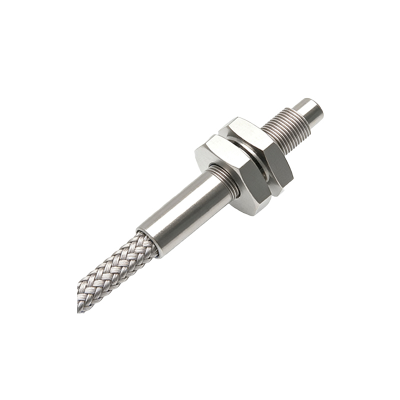
Begin by mechanically mounting the units. Most sensors have standard threaded barrels or pre-drilled holes for bracket mounting. Use the provided or recommended mounting brackets to secure each unit firmly. It is absolutely critical that the transmitter and receiver are positioned directly opposite each other on the same horizontal and vertical axis. Even a slight angular misalignment can drastically reduce signal strength. Use a spirit level to ensure both units are perfectly level. For long-range applications, temporary use of a visible red light beam or a laser alignment tool (if available) is highly recommended to visually confirm the path. Tighten all fasteners securely to prevent movement due to vibration, but avoid over-torquing which could damage the housing. Ensure there is no stress on the sensor body or its conduit connections.
Electrical Wiring and Connection
With the units physically mounted, proceed to electrical connections. First, ensure all power is locked out and tagged out (LOTO) according to safety protocols. Through-beam sensors typically have three to four wires: brown for DC positive (+V), blue for DC common (0V), black for the output signal (often NPN or PNP), and sometimes white for an output or function wire. Always refer to the manufacturer's wiring diagram on the sensor label or datasheet. Use shielded cable for the electrical connections, especially in environments with electrical noise from motors or drives. Connect the shield to ground at the control panel end only to prevent ground loops. Route sensor cables away from power lines and noisy circuits. For the receiver unit, ensure the output is correctly connected to your PLC, relay, or controller input. After wiring, perform a continuity check with a multimeter to verify there are no short circuits.
Alignment and Optical Adjustment
This is the most delicate step. Apply power to the system. Both the transmitter and receiver usually have LED indicators. A steady "power on" LED indicates proper voltage. The receiver will have an alignment or signal strength indicator—often a green LED that is solid when aligned, or a bar-graph display. Carefully adjust the position of the receiver (and sometimes the transmitter) in minute increments. Many sensors have built-in adjustment screws for fine-tuning the horizontal and vertical angle. The goal is to maximize the received light intensity. On models with a signal strength meter, adjust until you achieve the maximum possible reading. This provides a "safety margin" for the signal, ensuring reliable detection even if minor vibrations or thermal expansion occur later. Once optimal alignment is confirmed, securely tighten any adjustment screws or locking nuts on the brackets.
Functional Testing and Troubleshooting
Do not assume the sensor is operational after alignment. Perform comprehensive functional testing. Introduce the target object (the item to be detected) into the beam path at various speeds and positions. Verify that the receiver's output switches states reliably and that this change is correctly registered by your control system. Test for potential false triggers by moving objects near, but not through, the beam path. Common issues include weak signal (re-alignment needed), electrical noise (check shielding and grounding), and insufficient power supply (verify voltage at the sensor terminals). If the sensor has a sensitivity potentiometer, adjust it only if necessary to avoid nuisance tripping, but remember that maximizing optical alignment is always preferable to cranking up electronic sensitivity.
Final Securing and Documentation
After successful testing, perform a final check of all mechanical fasteners and electrical connections. Apply thread-locking compound to critical adjustment screws if permitted by the application environment. Ensure all cable glands are tightened to maintain the sensor's IP rating. Document the installation. Note the sensor model numbers, serial numbers, installation date, alignment settings (if applicable), and any specific observations. This documentation is invaluable for future maintenance or troubleshooting. Finally, establish a routine inspection schedule to check for physical damage, cleanliness of lenses, and signal strength, ensuring the through-beam sensor continues to provide reliable service in your automated system.