Introduction to 12V Infrared Photoelectric Sensors
Infrared photoelectric sensors are widely used in automation and control systems for detecting objects, counting, and positioning. These sensors operate by emitting an infrared light beam and detecting its reflection or interruption. The 12V DC variant is particularly common in industrial and automotive applications due to its compatibility with standard power supplies. Understanding the correct wiring diagram is crucial for ensuring reliable operation and preventing damage to the sensor or connected equipment. This guide provides a detailed overview of the wiring process, including key components and safety considerations.
Key Components and Pin Configuration
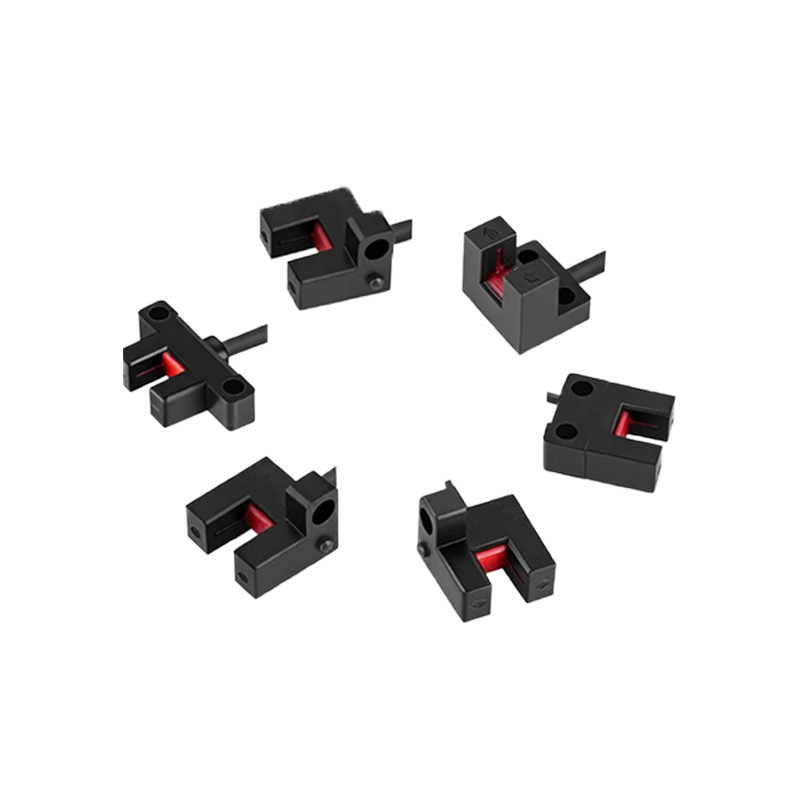
A typical 12V infrared photoelectric sensor consists of three main wires: power, ground, and output. The power wire (often red or brown) connects to the positive terminal of a 12V DC power source, while the ground wire (black or blue) links to the negative terminal. The output wire (usually white, yellow, or gray) transmits the signal to a controller, such as a PLC or relay. Some sensors may include additional wires for functions like timer adjustment or dual output modes. Always refer to the manufacturer's datasheet for specific pin configurations, as variations exist between models. Incorrect wiring can lead to malfunction or permanent failure.
Step-by-Step Wiring Instructions
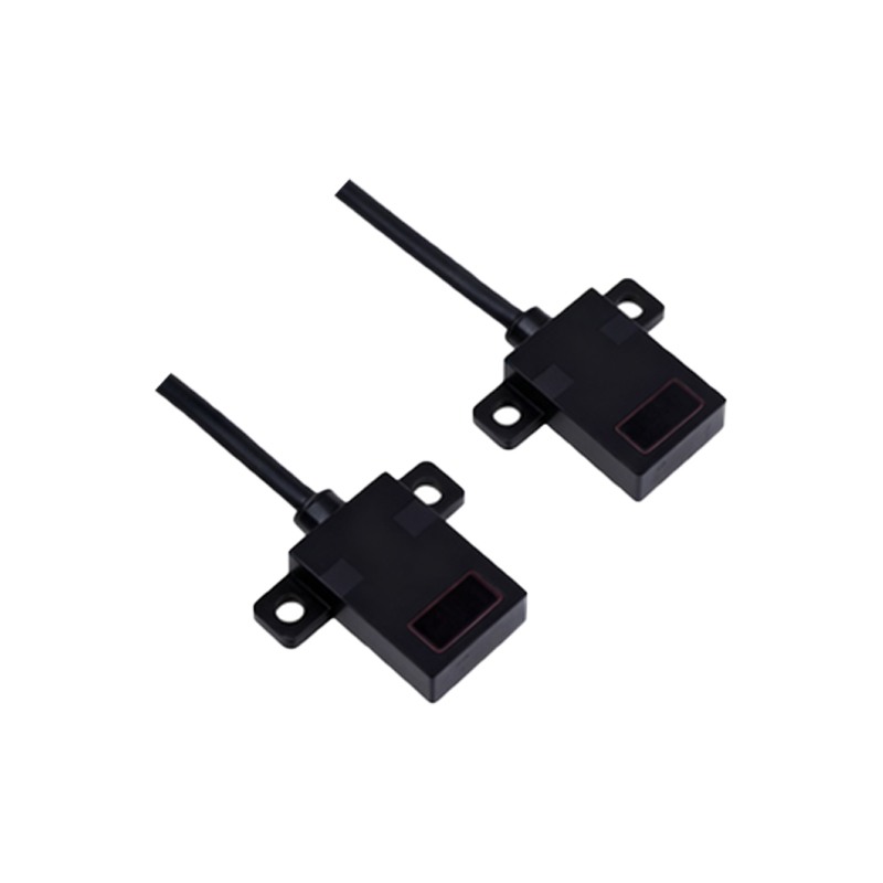
Begin by disconnecting the power source to avoid electrical hazards. Identify the sensor's wires using the provided documentation. Connect the power wire to the 12V DC supply's positive terminal and the ground wire to the negative terminal. Ensure connections are secure to prevent voltage drops. For the output, link the wire to the input terminal of your control device. If using a relay, connect the output to the coil terminal. Test the circuit with a multimeter to verify voltage levels before powering on. Once confirmed, apply power and observe the sensor's indicator LED for proper operation. Adjust alignment if necessary for optimal detection.
Common Wiring Diagrams and Applications
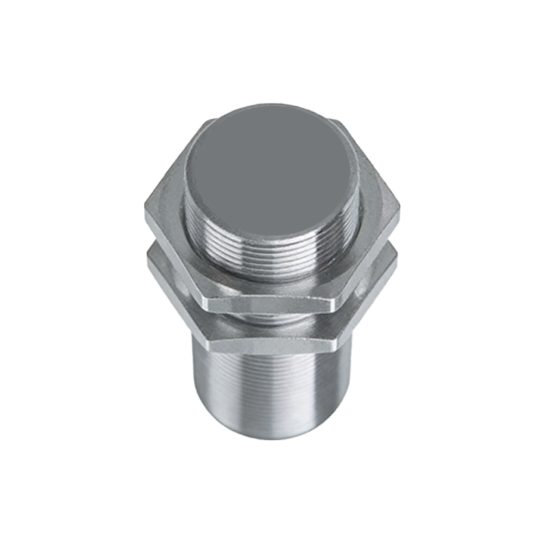
Two primary wiring setups are prevalent: normally open (NO) and normally closed (NC). In NO configuration, the output is off until an object is detected, triggering the signal. This is ideal for alarm systems or start triggers. In NC setup, the output is on until detection interrupts it, suitable for safety interlocks. Diagrams often include protective elements like fuses or diodes to safeguard against reverse polarity or overloads. Applications range from conveyor belt monitoring to vehicle detection in parking facilities. Always match the diagram to your sensor's specifications, as using an incorrect setup can cause erratic behavior.
Troubleshooting and Safety Tips
If the sensor fails to operate, check for loose connections, incorrect voltage, or misalignment. Use a multimeter to measure voltage at the sensor terminals; it should read approximately 12V DC. Ensure the detection path is free of obstructions and environmental factors like dust or moisture. Avoid exposing the sensor to direct sunlight, which can interfere with infrared signals. For safety, install fuses in the power line and use insulated tools during wiring. Regularly inspect connections for wear or corrosion. Consulting the manufacturer's troubleshooting guide can resolve persistent issues, preventing downtime in critical systems.
Conclusion and Best Practices
Proper wiring of a 12V infrared photoelectric sensor is essential for efficient and safe automation. Always follow the specific diagram provided by the manufacturer, double-check connections, and test thoroughly before full deployment. Incorporate protective devices to extend sensor lifespan and maintain system reliability. By adhering to these guidelines, you can ensure optimal performance in diverse industrial settings. For complex installations, consider consulting a professional engineer to avoid costly errors and enhance operational continuity.