Introduction to Through-Beam Photoelectric Sensors
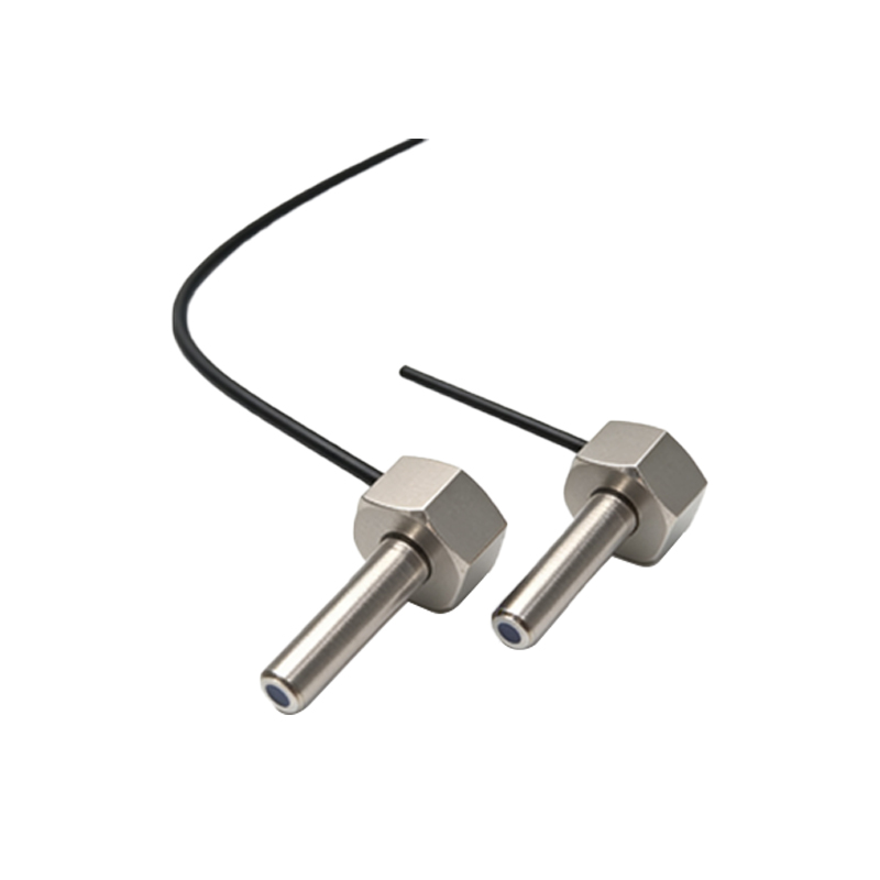
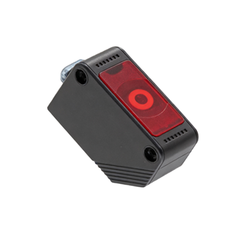
Through-beam photoelectric sensors are fundamental components in industrial automation, widely used for object detection, counting, and positioning. They consist of two separate units: a transmitter that emits a light beam (typically infrared, red, or laser) and a receiver placed directly opposite. An object is detected when it interrupts the beam between these two units. In electrical and control system design, creating accurate CAD drawings of these sensors is crucial for panel layout, machine design, and integration into larger electrical schematics. This guide provides a detailed, industry-standard approach to drafting a through-beam sensor pair in CAD software like AutoCAD Electrical, SolidWorks Electrical, or standard AutoCAD.
Gathering Essential Technical Data
Before beginning any CAD drawing, it is imperative to collect all necessary technical specifications from the sensor's datasheet. Key dimensions include the overall length, width, and height of both the transmitter and receiver housings. Note the exact diameter and position of the mounting holes, as well as the thread type if applicable. Pay close attention to the sensing face dimensions and the location of the LED indicators. Furthermore, document the connector type, its dimensions, and the cable outlet direction. Having a PDF copy of the 2D dimensional drawing from the manufacturer's website is highly recommended for tracing or reference to ensure dimensional accuracy in your final CAD block.
Setting Up the CAD Drawing Environment
Launch your CAD software and create a new drawing. It is best practice to set up dedicated layers for different elements. Create layers such as "OUTLINE," "MOUNTING_HOLES," "CONNECTOR," "TEXT," and "CENTERLINES." Assign appropriate colors and line weights to each layer; for instance, use a continuous thick line for the outline and a centerline style for axes. Set your units to millimeters, as this is the industry standard for most sensor components. Ensure your drawing limits or layout space are adequate for the sensor size and any additional notes.
Drawing the Transmitter Unit Outline
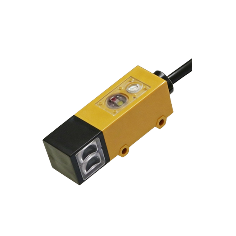
Start by drawing the main housing of the transmitter. Using the "OUTLINE" layer, begin with a rectangle or a series of lines and arcs based on the sensor's body shape, which is often cylindrical or rectangular. Use the dimensions from the datasheet precisely. Next, on the "MOUNTING_HOLES" layer, draw the mounting holes. Use the circle command for through-holes. Employ object snaps like "Center" and "Quadrant" for accuracy. If the sensor has a mounting bracket, draw its profile separately. Add fillets or chamfers to edges if specified. The sensing face (the lens) should be represented clearly, often with a different line style or a small detail drawing in a callout.
Drawing the Receiver Unit Outline
Repeat the process for the receiver unit. While the transmitter and receiver are often identical in housing dimensions, verify this in the datasheet. Draw the receiver's outline and mounting holes on their respective layers. A critical detail is to clearly differentiate the receiver from the transmitter in your drawing. This can be done by adding a label ("RX") inside the outline or by using a slightly different shading or hatch pattern in the final presentation drawing. Ensure the alignment between the transmitter and receiver is conceptually clear, often shown with a dashed centerline representing the beam path in an assembly drawing.
Adding Connectors and Cable Details
Switch to the "CONNECTOR" layer. Draw the electrical connector based on its type (e.g., M8, M12). This typically involves drawing the circular profile, pin holes, and the locking thread or groove. Indicate the cable outlet, showing its diameter and direction (straight, right-angle). For schematic symbols, which are different from mechanical drawings, you would create a separate block using standard IEC or ANSI symbols for a photoelectric sensor, showing the transmitter as a diode symbol and the receiver as a phototransistor, connected by dashed lines.
Applying Dimensions and Annotations
Dimensioning is critical for manufacturing and installation. Use the "TEXT" layer. Add all key dimensions: overall sizes, hole spacings, hole diameters, and critical distances to sensing faces. Use aligned and diameter dimension commands. Follow good dimensioning practices: avoid over-dimensioning, place dimensions clearly outside the part outline, and use leaders for small features. Add annotations such as the part number (e.g., "Model: XYZ-TB50"), supply voltage, output type, and beam type. Include a title block with your company name, drawing title, scale, and revision history.
Creating Blocks and Managing Libraries
Once both units are fully drawn and dimensioned, convert each sensor unit into a CAD block. Use the "BLOCK" or "WBLOCK" command. Give the blocks logical names like "PHOTO_SENSOR_TX_50M" and "PHOTO_SENSOR_RX_50M." Define a clear insertion point, typically the center of a mounting hole or the geometric center of the housing. Save these blocks to your company's or your personal standardized component library. This allows for quick insertion into future machine layout drawings, ensuring consistency and saving significant time. For 3D modeling, extrude the 2D profiles to create solid bodies and assemble them in their working orientation.
Final Review and Best Practices
Conduct a thorough review. Check all dimensions against the datasheet. Verify that layers are used correctly and that the drawing is clean without overlapping lines. Ensure the drawing communicates effectively: a technician should be able to understand the mounting requirements and physical size without ambiguity. A best practice is to include a small isometric view or a 3D render as an inset to provide spatial context. Always remember that a well-drawn CAD model facilitates error-free procurement, panel fabrication, and on-site installation, reducing project risks and costs.