Understanding Proximity Sensor Fundamentals
Proximity sensors are critical components in industrial automation, detecting the presence or absence of objects without physical contact. Their operation relies on electromagnetic fields, infrared light, or ultrasonic sound waves. A sensor's external condition often provides the first visual clue to its internal health. Engineers must recognize that physical integrity directly correlates with functional reliability. Key types include inductive, capacitive, photoelectric, and ultrasonic sensors, each with distinct visual identifiers for their sensing elements and housing.
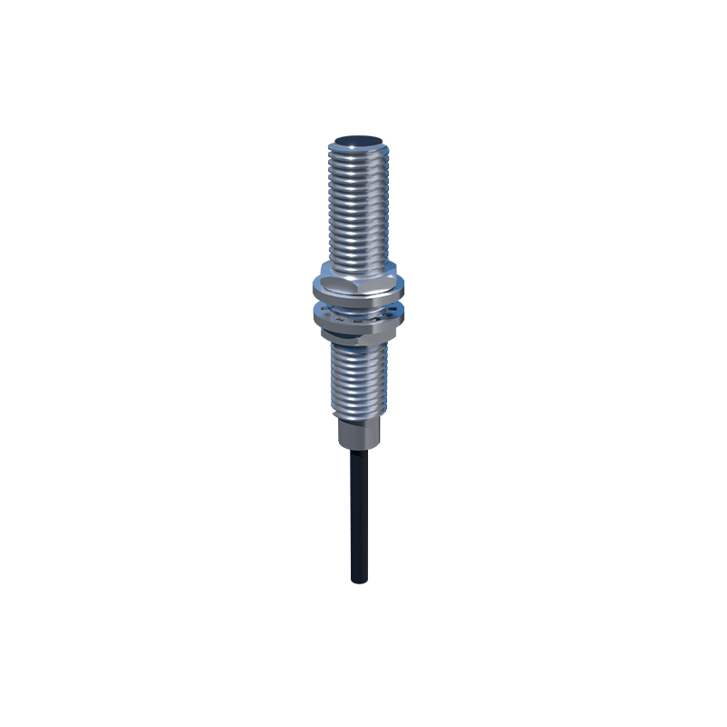
Inspecting the Sensor Housing and Connectors
Begin your visual assessment with the sensor's body. Look for cracks, deep scratches, or deformation in the plastic or metal housing. These can indicate impact damage or exposure to excessive stress, potentially compromising internal electronics and environmental seals. Pay close attention to the connector area. Corrosion on the metal pins or a cracked, melted, or loose connector body suggests exposure to moisture, chemical contaminants, or electrical overload. A warped housing near the sensing face can misalign internal components, leading to inconsistent detection performance.
Examining the Sensing Face for Contamination
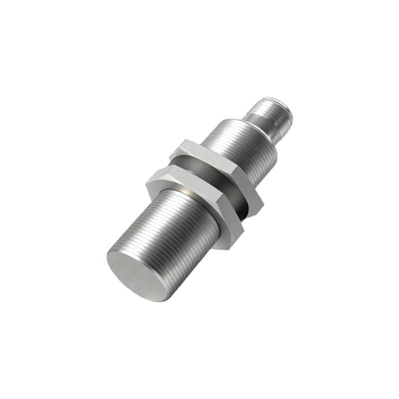
The sensing face is the most vulnerable part. For inductive and capacitive sensors, this is typically a flat, smooth surface. A clean, unmarred face is essential. Look for buildup of metal shavings, oil, grease, paint, or other process materials. This contamination can dampen the electromagnetic field or create a false detection barrier. For photoelectric sensors, inspect the lens for scratches, cloudiness, or dirt accumulation. Even a thin film can scatter or block the light beam. Ultrasonic sensor transducers should be free of any material that could absorb or deflect sound waves.
Analyzing LED Indicator Status in Context
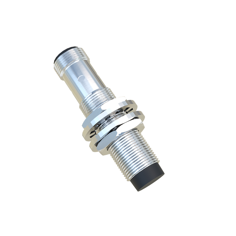
Most modern proximity sensors feature LED status indicators. A single image can be informative, but understanding the context is vital. A solid illuminated LED when no target is present typically indicates a fault or a "dark-on" mode setting. A flashing LED might signal a short-circuit, overload, or built-in diagnostic warning. Conversely, an LED that does not illuminate when power is applied and a target is within range strongly suggests a failed sensor. Compare the LED's indicated state with the expected state for the depicted scenario.
Identifying Signs of Overheating and Burn Marks
Discoloration is a major red flag. Look for yellowing, browning, or blackening of the plastic housing, especially near the electrical connections or the sensing head. This is a clear visual symptom of overheating, often caused by excessive current, poor connections, or operating in an environment beyond its temperature rating. Melted plastic or visible charring on circuit boards (if the housing is transparent or opened) signifies catastrophic failure. Such thermal damage permanently alters material properties and component specifications.
Evaluating Mounting Integrity and Alignment
A sensor's performance is highly dependent on correct installation. In images, check if the sensor is securely mounted. Loose mounting brackets or misalanged screws can cause vibration-induced failure. Assess the alignment relative to the target. An inductive sensor mounted too far from a metal target, or a photoelectric sensor misaligned with its reflector or receiver, will not function correctly. Look for witness marks or shiny spots on the mounting hardware, which indicate movement and loosening over time.
Comparing with Known-Good Reference Images
The most effective method for visual judgment is comparison. Maintain a library of images showing new, properly functioning sensors of the same model. Compare the sensor in question against this benchmark. Differences in color, component placement, label clarity, or LED brightness can reveal issues like counterfeits, previous repairs with non-OEM parts, or prolonged UV exposure degrading materials. Consistency in appearance across a production line of identical sensors is also a good health indicator; the outlier often has a problem.
Recognizing Limitations of Visual Inspection
While a picture can reveal many faults, it cannot confirm all operational parameters. Visual inspection cannot measure sensing distance, hysteresis, repeatability, or response time. It cannot diagnose internal circuit faults like a failed oscillator in an inductive sensor or a degraded emitter in a photoelectric sensor. Therefore, use image-based assessment as a powerful first-pass screening tool. It can quickly identify sensors that are clearly damaged or contaminated, saving time before committing to electrical testing with a multimeter or oscilloscope on the bench or in the field.