Introduction to Photoelectric Sensors in Calciner Furnaces
Photoelectric sensors are critical components in modern calciner furnace operations, providing non-contact detection and monitoring of materials, flames, and equipment status. These sensors operate by emitting a light beam, typically from an LED or laser source, and detecting changes in the received light intensity caused by the presence or absence of a target object. In the harsh environment of a calciner, where extreme temperatures, dust, and corrosive gases are prevalent, robust sensor design is paramount. The schematic of such a sensor is not merely a circuit diagram; it represents a system engineered for reliability, precision, and resilience. Understanding this schematic is essential for engineers involved in maintenance, troubleshooting, and optimization of calcination processes, which are vital in industries like cement production, alumina processing, and waste incineration.
Core Components and Schematic Layout
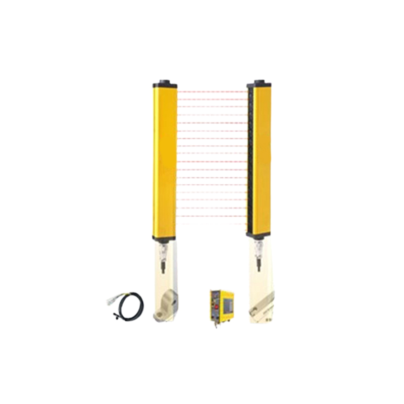
A standard photoelectric sensor schematic for calciner applications can be divided into several key functional blocks. The primary components include the light emitter circuit, the light receiver circuit, the signal processing unit, and the output driver. The emitter circuit centers around a high-intensity, pulsed infrared LED or a laser diode. A constant current driver circuit, often involving a transistor or dedicated IC, ensures stable light output despite voltage fluctuations common in industrial settings. A collimating lens is used to focus the emitted light into a narrow beam, enhancing sensing range and directionality. The receiver section features a phototransistor or photodiode paired with a focusing lens. This component converts the received light intensity into a proportional electrical current. Crucially, an optical filter is often incorporated to block ambient infrared radiation from the hot furnace walls, preventing false triggering.
Signal Conditioning and Processing Circuitry
The weak current signal from the photodetector requires significant amplification and conditioning. The schematic details a multi-stage amplifier, usually based on operational amplifiers, to boost the signal to a usable level. Following amplification, a comparator circuit is employed. This circuit compares the amplified signal against a preset reference voltage, which corresponds to a threshold light level. When the received light is interrupted (e.g., by a falling clinker nodule or a broken flame), the signal drops below this threshold, causing the comparator's output to switch state. Advanced schematics include synchronous demodulation or modulation/demodulation circuits. Here, the emitter LED is pulsed at a specific high frequency (e.g., 5kHz), and the receiver circuit is tuned to respond only to light modulated at that same frequency. This technique, clearly shown in the timing diagrams within the schematic, makes the sensor highly immune to interference from ambient light, including the intense glow of the calciner itself.
Output Stage and Protection Features
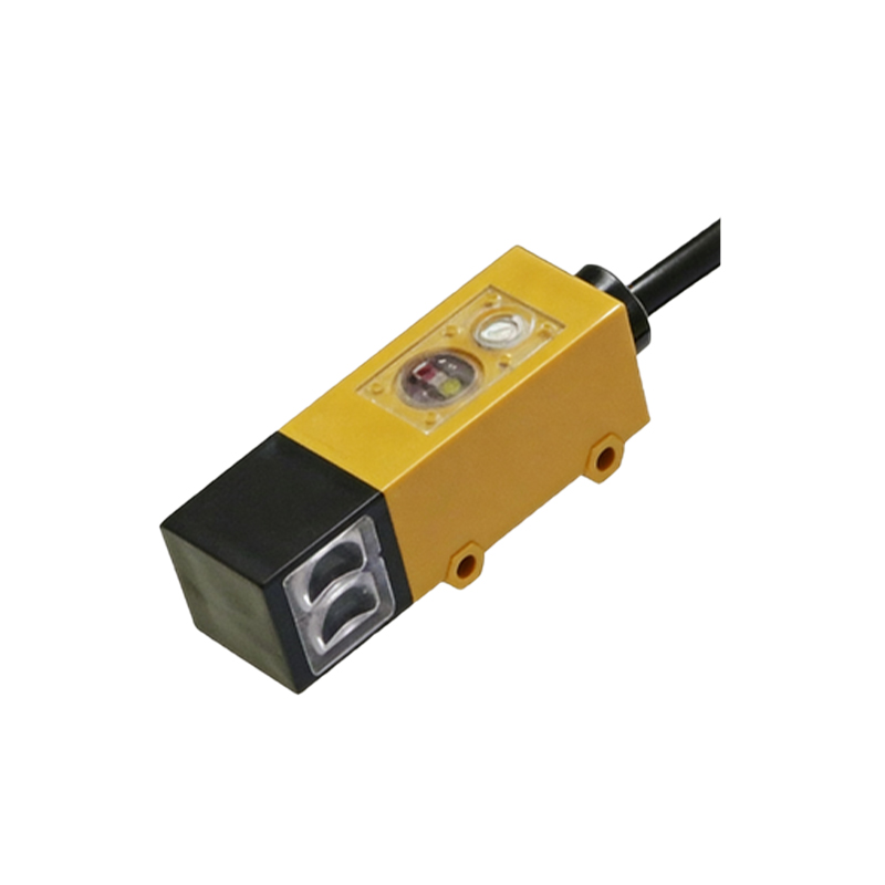
The digital signal from the comparator drives the output stage. Common outputs include a transistor (NPN or PNP) for switching a load, or a solid-state relay for higher current isolation. The schematic explicitly shows protective elements such as flyback diodes for inductive loads, transient voltage suppressors (TVS diodes) for surge protection, and current-limiting resistors. For communication in networked systems, the schematic may integrate a protocol interface like IO-Link, showing the connection points for data, power, and ground. A dedicated power supply regulation section is also a critical part of the schematic. It ensures stable DC voltages for the sensitive analog circuitry from the typically noisy 24V DC industrial supply, using voltage regulators, capacitors for filtering, and sometimes ferrite beads to suppress high-frequency noise.
Environmental Hardening in the Design
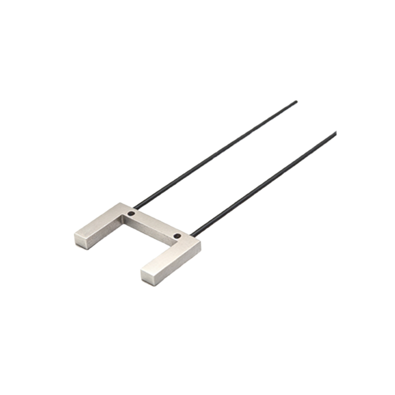
The schematic reflects design choices made for environmental hardening. This includes specifying components with wide operating temperature ranges. The selection of lens materials, such as tempered glass or synthetic sapphire, capable of withstanding thermal shock and abrasive dust, is implied in the mechanical notes often accompanying the electrical schematic. Furthermore, the circuit layout on the PCB, suggested by the schematic's netlist, is designed to minimize noise coupling. Critical signal paths are kept short, and ground planes are used extensively. For sensors using fiber optic cables to remotely locate the electronics from the furnace hot zone, the schematic details the connections to the fiber optic transceiver modules, specifying transmitter and receiver compatibility.
Application-Specific Configurations
Depending on the specific calciner application, the schematic may vary. For flame monitoring, the receiver might be tuned to a specific spectral band (e.g., ultraviolet or specific infrared wavelengths) characteristic of the fuel, and the schematic will show the appropriate optical filters. For bulk material level detection, a retro-reflective sensor schematic includes the wiring for a dedicated reflector. Through-beam sensor schematics, where emitter and receiver are separate units, detail the interconnection and alignment requirements. Each variant maintains the core principles but adapts the peripheral components and, in some cases, the processing logic to meet the unique demands of the sensing task, such as differentiating between a steady flame and a passing hot clinker.
Conclusion: The Schematic as a Diagnostic Tool
Mastering the photoelectric sensor schematic empowers engineers beyond installation. It serves as a fundamental diagnostic tool. By understanding the signal flow from emitter to output, a technician can systematically test each stage using an oscilloscope or multimeter. For instance, verifying the presence of a pulsed signal at the emitter driver, checking the amplified signal at the comparator input, or testing the output transistor's switching can isolate faults precisely. In the demanding context of a calciner furnace, where unscheduled downtime is costly, this ability to quickly interpret the schematic and troubleshoot is invaluable for ensuring continuous, safe, and efficient operation.