Introduction to Photoelectric Sensor Fundamentals
Photoelectric sensors are pivotal components in modern automation and control systems, leveraging light beams to detect the presence, absence, or distance of objects. The core principle involves an emitter light source, typically an LED or laser diode, and a receiver, such as a phototransistor or photodiode. The receiver interprets changes in the received light intensity caused by an object interrupting or reflecting the beam. In the Proteus Design Suite, simulating these circuits allows engineers to validate designs, troubleshoot potential issues, and optimize performance before physical prototyping. This virtual environment provides access to a vast library of components, including various light emitters and detectors, enabling precise modeling of real-world sensor behavior under different conditions.
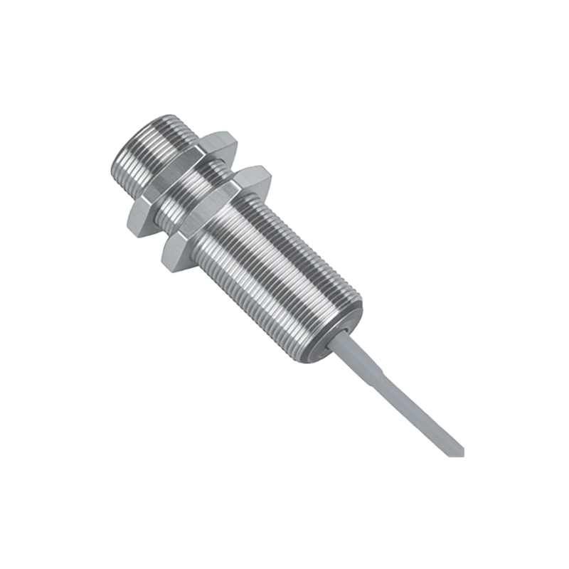
Key Components for Sensor Circuit Simulation
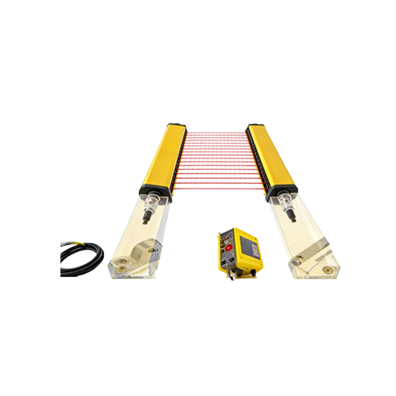
Building an effective photoelectric sensor simulation in Proteus requires selecting appropriate virtual components. The primary elements include a light-emitting device. For common applications, an infrared LED (IRED) is frequently chosen for its efficiency and immunity to ambient light interference. On the receiver side, a phototransistor is a popular choice due to its inherent amplification, providing a stronger output signal compared to a photodiode. Essential supporting components comprise current-limiting resistors for the emitter to prevent damage, a pull-up or pull-down resistor for the receiver's output stage, and often an operational amplifier (op-amp) configured as a comparator. This comparator circuit is crucial for converting the analog signal from the phototransistor into a clean, digital logic signal suitable for microcontrollers or other digital logic circuits.
Designing a Basic Reflective Sensor Model
A reflective sensor configuration places the emitter and receiver side-by-side, detecting objects that reflect the emitted light back to the receiver. In Proteus, start by placing an IR LED and a phototransistor on the schematic. Connect the IRED's anode through a 220-ohm resistor to a 5V power source and its cathode to ground. For the phototransistor, connect its collector to the positive supply via a 10k ohm pull-up resistor and its emitter to ground. The output signal is taken from the collector node. When no object is present, the phototransistor receives minimal reflected light, remains in a high-impedance state, and the output is pulled high. When a reflective object enters the detection zone, light reflects onto the phototransistor, causing it to conduct and pull the output voltage low. This simple circuit can be simulated to observe the voltage transition at the output node.
Implementing Signal Conditioning with a Comparator
The raw output from a phototransistor is analog and can be susceptible to noise and varying ambient light levels. Implementing a comparator stage significantly enhances reliability. In Proteus, add an op-amp like the LM358 to the circuit. Configure it as a comparator by connecting the phototransistor's output (collector) to the inverting input of the op-amp. A potentiometer or a voltage divider network is connected to the non-inverting input to set a precise reference voltage threshold. The output of the op-amp will swing to the high rail (e.g., 5V) when the sensor signal is below the threshold (object detected) and to the low rail (0V) when above it (no object). This process converts the analog signal into a sharp, digital pulse. Simulation allows for easy adjustment of the reference voltage to fine-tune the sensor's sensitivity for different object colors and distances.
Advanced Simulation: Through-Beam Sensor with Modulation
For long-range or high-ambient-light applications, a through-beam sensor with modulated light is superior. This design separates the emitter and receiver, facing each other. Detection occurs when an object breaks the light beam. To combat ambient light interference, the LED is driven by a pulsed signal, often generated by a 555 timer circuit or a microcontroller pin in Proteus. The receiver circuit includes a filter tuned to the same frequency. In simulation, you can design a 555 astable circuit to pulse the IRED at 5-10 kHz. The receiver side uses a phototransistor followed by a band-pass filter and a demodulator circuit (like a peak detector) to respond only to the modulated signal. This advanced setup dramatically improves noise immunity and can be thoroughly tested in Proteus by introducing simulated ambient light noise sources.
Interfacing with Microcontrollers for System Integration
The final step in a complete sensor system is interfacing the conditioned digital output with a microcontroller (MCU) like an Arduino or PIC model available in Proteus. Connect the comparator's output pin to a digital input pin of the MCU. Within the Proteus simulation, you can then write and debug embedded firmware for the virtual MCU. This code can read the sensor state, implement debouncing logic, trigger actuators, or communicate data to a virtual terminal or LCD display. This holistic simulation validates not just the analog sensor circuitry but also the digital logic and software that form the complete control system. Engineers can test edge cases, such as rapidly moving objects or intermittent detection, ensuring robust performance before hardware commitment.
Simulation Analysis and Performance Validation
Proteus offers powerful tools for analyzing circuit performance. Use the built-in oscilloscope and voltage probes to visualize the signals at key points: the pulsed LED drive, the raw phototransistor output, and the final digital signal from the comparator. The graph can clearly show the signal's behavior when an object is detected versus the idle state. Additionally, use the DC voltmeter to check biasing points. To test robustness, you can modify component properties, such as increasing the series resistor for the LED to simulate a weaker emitter or changing the phototransistor's model to one with different sensitivity. Performing a transient analysis over time will show the system's dynamic response. This iterative simulation process is invaluable for identifying design flaws, such as insufficient hysteresis or slow response times, and correcting them efficiently.