Introduction to M1 Proximity Sensors
M1 proximity sensors represent a specific and widely utilized category within the vast field of industrial automation. These non-contact sensing devices are engineered to detect the presence or absence of a metallic target without any physical contact. The "M1" designation often refers to a particular form factor, mounting style, or performance specification standardized across manufacturers, ensuring compatibility and ease of integration into various machinery and control systems. Their primary function is to provide a reliable electrical signal to a programmable logic controller (PLC) or other control unit, triggering actions such as counting, positioning, limiting, or object detection on assembly lines, packaging machines, and robotic cells.
Core Operating Principles
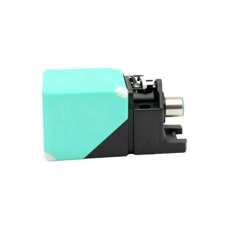
The most common technology employed in M1 inductive proximity sensors is the electromagnetic induction principle. The sensor contains an oscillator circuit that generates a high-frequency electromagnetic field at its active face. When a ferrous or non-ferrous metal target enters this field, eddy currents are induced on the target's surface. This causes a change in the oscillation amplitude within the sensor, which is detected by a threshold circuit. This change triggers the sensor's solid-state output to switch states, providing a clean, bounce-free signal. Key specifications include sensing distance, which is typically short-range (e.g., 1mm to 15mm for M1 styles), repeat accuracy, and switching frequency. The robust, all-metal housing of a standard M1 sensor provides excellent resistance to mechanical stress, cutting fluids, and industrial contaminants.
Key Features and Technical Specifications
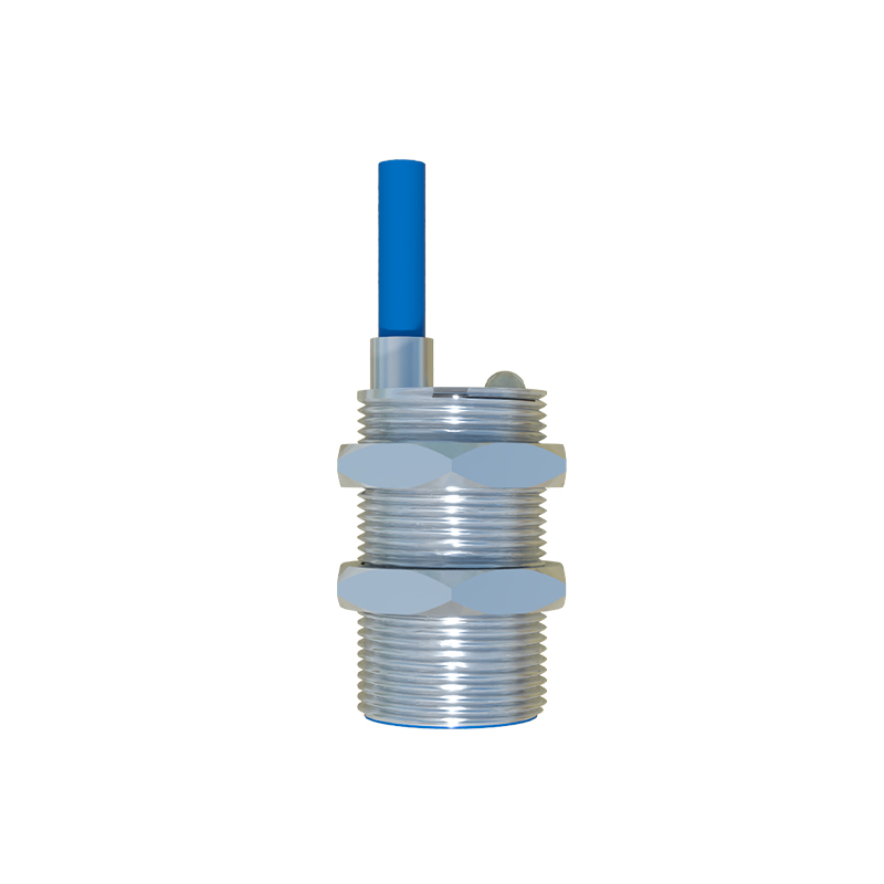
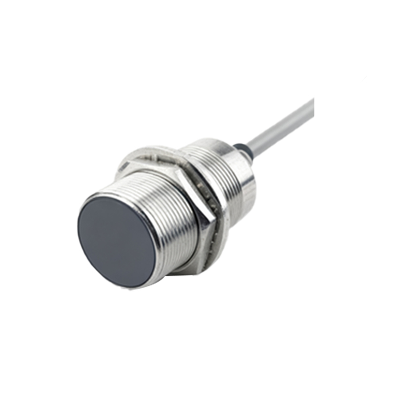
A standard M1 cylindrical proximity sensor is characterized by its compact M12x1 threaded barrel, making it a "mini" form factor sensor. Common features include a shielded (flush-mountable) or unshielded (non-flush) design. Shielded sensors can be mounted flush in metal without affecting their sensing range, while unshielded types offer a longer range but require a non-metallic surrounding. Output configurations are typically NPN (sinking) or PNP (sourcing) transistor outputs, with 3-wire or 4-wire designs, alongside traditional 2-wire AC/DC versions. Key technical parameters to evaluate are the rated operating voltage (e.g., 10-30V DC), current consumption, output current capacity, IP rating for ingress protection (commonly IP67), temperature range, and the presence of diagnostic LEDs. These specs determine the sensor's suitability for specific environmental conditions.
Advantages in Industrial Environments
The adoption of M1 proximity sensors offers numerous advantages over mechanical limit switches or photoelectric sensors in certain contexts. Their non-contact nature eliminates mechanical wear and tear, leading to a dramatically longer operational lifespan and reduced maintenance. They are immune to problems caused by dirt, dust, oil, and moisture (given a suitable IP rating), providing stable performance in harsh conditions where optical sensors might fail. They offer very high switching speeds, often in the kilohertz range, enabling detection of fast-moving objects on high-speed production lines. Furthermore, their solid-state design ensures millions of reliable switching cycles with exceptional repeat accuracy, which is critical for precision automation tasks like robotic tool positioning or part verification.
Common Application Scenarios
M1 proximity sensors find applications across virtually every manufacturing sector. A classic use is end-position detection on pneumatic or hydraulic cylinders, where a sensor detects the piston's metal ring to confirm extension or retraction. They are extensively used for part presence/absence verification on conveyors, in automated assembly stations, and in packaging machinery. Rotary speed monitoring is another key application, where sensors count gear teeth or detect bolts on a rotating shaft. In metalworking, they serve as tool breakage detectors or workpiece clamps confirmation. Their small size makes them ideal for space-constrained applications inside machine tools, material handling equipment, and automated guided vehicles (AGVs).
Installation and Wiring Considerations
Proper installation is crucial for optimal performance. Engineers must ensure the correct mounting, respecting the specified sensing distance and accounting for the sensor's blind zone. For flush-mounted shielded sensors, adjacent metal must not extend beyond the sensor's face. Adequate clearance between multiple sensors is necessary to prevent mutual interference. Wiring must conform to the sensor's data sheet: brown wire (or +) to positive voltage, blue wire (or -) to common/negative, and the black (or white) wire as the switched output load. It is essential to connect a protective load, such as a resistor or the PLC input, in series with the output. For DC sensors, attention must be paid to the correct polarity to prevent damage. Always follow local electrical codes and standards.
Troubleshooting and Maintenance Tips
While highly reliable, M