Understanding Miniature Proximity Sensor Fundamentals
Miniature proximity sensors are essential components in modern automation, providing non-contact detection of metallic or non-metallic objects. Before beginning any wiring procedure, it is crucial to understand the sensor's type—inductive, capacitive, or photoelectric—as this determines its detection target and influences wiring specifics. Equally important is identifying whether the sensor is NPN (sinking) or PNP (sourcing), and whether it features a Normally Open (NO) or Normally Closed (NC) output configuration. These specifications are always detailed on the sensor's datasheet and nameplate. A thorough review of this documentation is the mandatory first step to ensure correct integration and prevent equipment damage.
Essential Tools and Safety Precautions
Gather all necessary tools before starting: appropriate wire strippers, crimping tools, screwdrivers, and a multimeter for verification. Safety is paramount. Always disconnect and lock out all power sources to the control circuit and the sensor itself. Verify that the voltage is off using a multimeter. Ensure the work environment is clean and dry to avoid short circuits. Personal protective equipment, such as safety glasses and insulated gloves, is recommended. Confirm that the sensor's voltage rating (e.g., 10-30V DC) matches your power supply. Never exceed the specified voltage or current limits.
Deciphering the Connection Diagram and Wire Colors
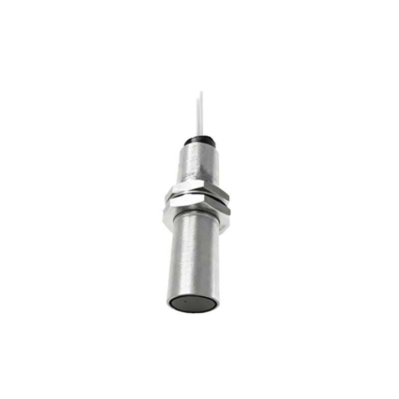
Miniature proximity sensors typically have three or four wires. The standard color coding for 3-wire DC sensors is Brown, Blue, and Black (sometimes White or another color for a second output). The Brown wire is universally connected to the positive DC supply voltage (+V). The Blue wire is connected to the negative DC supply voltage, or 0V (Common). The Black wire is the switched output signal line. For a 4-wire sensor, you will often find two output wires (e.g., Black for NO and White for NC). Always defer to the manufacturer's diagram printed on the sensor body or provided in the manual, as colors can occasionally vary by brand or region.
Wiring a 3-Wire DC PNP (Sourcing) Sensor
A PNP sensor switches the positive voltage to the load. Begin by connecting the Blue wire to the 0V (DC Common) of your power supply. Next, connect the Brown wire to the positive terminal of your DC power supply (e.g., +24V). The Black output wire is then connected to one terminal of your load device, such as a PLC input, relay coil, or indicator lamp. The other terminal of the load must be connected back to the 0V (DC Common) of the power supply. When a target is detected, the PNP sensor will source current, completing the circuit by providing +24V from the Black wire to the load, which then flows back to 0V.
Wiring a 3-Wire DC NPN (Sinking) Sensor
An NPN sensor switches the negative or 0V line to the load. The power connections remain identical: Brown to +V and Blue to 0V. The critical difference is in the output connection. Connect one terminal of your load device directly to the positive supply voltage (+V). Then, connect the other terminal of the load to the Black output wire of the sensor. When a target is detected, the NPN sensor sinks current, completing the circuit by connecting the load to 0V through the Black wire. This allows current to flow from +V, through the load, through the sensor's Black wire, and out through its Blue wire to 0V.
Connecting to a Programmable Logic Controller (PLC)
Integration with a PLC is a common application. First, identify whether your PLC digital input card is configured for sinking or sourcing. A sinking input card (common to +V) typically pairs with a PNP sensor. A sourcing input card (common to 0V) typically pairs with an NPN sensor. Mismatching can lead to non-operation. Connect the sensor's Brown and Blue wires to the PLC's auxiliary power supply or a dedicated DC supply with shared common. Connect the sensor's Black output wire to the designated PLC input terminal. Always ensure the commons (0V) of the sensor power supply and the PLC input circuit are connected together for a unified reference potential.
Final Verification and Troubleshooting Steps
After all connections are securely tightened, double-check the wiring against the diagram. Before applying power, use a multimeter in resistance or continuity mode to check for short circuits between wires. Apply power and observe the sensor's indicator LED