Understanding Photoelectric Sensor Mounting Requirements
The selection of the correct screw size for mounting a photoelectric sensor is a critical, yet often overlooked, aspect of industrial automation system design. While the primary focus is typically on the sensor's sensing range, response time, and output type, secure and precise mounting is fundamental to achieving reliable, long-term performance. An improperly mounted sensor can lead to misalignment, vibration-induced failures, or physical damage, resulting in costly downtime. The mounting hardware, specifically the screws, forms the mechanical interface between the sensor and its bracket, machine frame, or housing. This section delves into the core reasons why screw specification matters, emphasizing that the mechanical integrity of the installation is as vital as the electrical and optical integrity of the sensor itself.
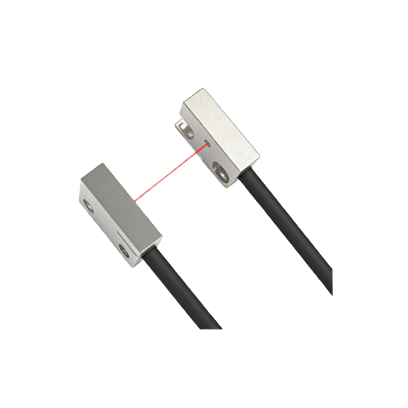
Standard Screw Sizes for Common Sensor Housings
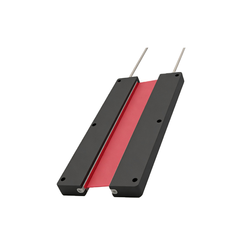
Most industrial photoelectric sensors feature standardized mounting holes or threaded inserts to simplify installation. The prevalent screw sizes are metric, aligning with global manufacturing standards. For compact, tubular sensors (often with M8, M12, M18, or M30 threaded barrels), the mounting bracket typically uses machine screws that thread into a separate clamp or bracket. The screws securing the clamp itself are commonly in the range of M4 to M6. Larger, rectangular "block-style" sensors frequently incorporate through-holes or threaded mounting feet. For these housings, M4, M5, and M6 screws are the most widespread. A standard through-hole for an M4 screw, for instance, will have a clearance diameter of approximately 4.5mm. It is imperative to consult the specific sensor's datasheet or installation manual, as manufacturers like Omron, Sick, Keyence, or Banner will provide exact dimensional drawings specifying thread size, hole diameter, and recommended screw length.
Determining the Correct Screw Length and Thread Pitch
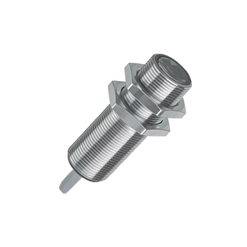
Selecting the appropriate screw length is crucial to ensure sufficient engagement without causing internal damage. A screw that is too short may not achieve the necessary clamping force, leading to a loose sensor. Conversely, a screw that is excessively long can protrude into the sensor's internal cavity, potentially damaging sensitive electronic components or optical elements. A general rule is that the screw should engage in the threaded material by a length at least 1.5 to 2 times the screw's nominal diameter. For an M5 screw, this means an engagement depth of 7.5mm to 10mm. Furthermore, attention must be paid to thread pitch (the distance between threads), denoted as "M5 x 0.8" where 0.8mm is the pitch. Using a screw with an incorrect pitch can strip the threads. Most sensor mounting holes use standard coarse pitches, but verification is essential, especially with sensors from different regional markets.
Material and Strength Considerations for Mounting Screws
The operating environment dictates the required material and strength grade of the mounting screws. In standard factory environments, zinc-plated or chromated steel screws (property class 8.8 or A2 stainless steel) offer a good balance of strength and corrosion resistance. For harsh environments involving washdowns, chemicals, or outdoor exposure, austenitic stainless steel (A2 or A4/316) is the preferred choice to prevent rust and seizure. In food and beverage or pharmaceutical applications where hygiene is paramount, polished stainless steel screws are often mandated. The tensile strength of the screw must be adequate to withstand operational vibrations and any incidental impact. Using a low-grade screw in a high-vibration application can lead to fatigue failure and sensor detachment. Always match the screw material to the sensor housing and mounting bracket material to avoid galvanic corrosion.
Best Practices for Installation and Torque Specifications
Proper installation technique ensures the longevity of both the screw and the sensor's mounting threads. First, ensure the mounting surface is clean, flat, and free of burrs. Use washers, preferably split lock washers or star washers, under the screw head to prevent loosening from vibration. Apply thread-locking adhesive (e.g., Loctite 243) for critical applications where vibration is severe. Most importantly, adhere to the manufacturer's recommended torque value. Over-tightening is a common error that can strip the aluminum or plastic threads commonly found in sensor housings, permanently damaging the unit. While specific torque values vary, a general guideline for steel screws into aluminum is approximately 2-3 Nm for M4 screws and 5-8 Nm for M6 screws. A calibrated torque wrench should be used for consistent, reliable results.
Troubleshooting Common Mounting-Related Issues
Several operational problems can be traced back to mounting and screw-related issues. Intermittent sensor failure or signal fluctuation is frequently caused by a loose mounting screw, allowing the sensor to move slightly and break the optical beam path. Consistent mis-sensing or reduced sensing range may indicate that the sensor is not perpendicular to the target due to an uneven mounting surface or an incorrectly tightened bracket screw. If a sensor fails prematurely without obvious environmental cause, inspect the mounting threads for stripping. In retrofit or replacement scenarios, never force a screw that does not thread in smoothly; the existing threads may be damaged or of a different standard (e.g., UNC instead of metric). Always clean out mounting holes with the correct tap if necessary before installing a new sensor.