Understanding Proximity Sensor Fundamentals
Proximity sensors are indispensable components in modern crane systems, providing non-contact detection of metallic objects to ensure operational safety and precision. These sensors function by generating an electromagnetic field. When a metallic target enters this field, it causes a change in the sensor's oscillation amplitude, which is then converted into a switching signal. For crane applications, inductive proximity sensors are predominantly used due to their robustness and reliability in harsh industrial environments filled with dust, moisture, and vibration. The core function within a crane setup is to detect the presence of a hook block, trolley, or the crane bridge itself near its travel limits, preventing collisions and enabling automated positioning. Understanding this operational principle is crucial before examining the specific wiring configurations that bring this functionality to life in a control circuit.
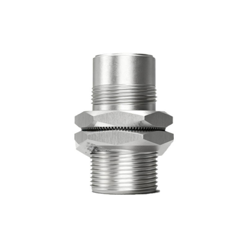
Key Components in a Standard Wiring Setup
A typical wiring diagram for integrating a proximity sensor into a crane control system involves several key components beyond the sensor itself. The primary elements include the proximity sensor (often a 3-wire or 4-wire DC type), a DC power supply (commonly 24V DC for industrial controls), the load (such as a relay coil, programmable logic controller (PLC) input module, or an indicator lamp), and the necessary cabling and connectors. The sensor body is usually marked with labels: brown wire for positive DC supply (+V), blue wire for the negative/ground (0V), and black wire for the load output signal. In a 4-wire sensor, an additional white wire may be present for a complementary output. It is vital to note that sensors can be sourced current (PNP, positive switching) or sunk current (NPN, negative switching), which dictates how they are connected to the PLC or relay. This distinction forms the backbone of any wiring schematic.
Detailed PNP (Sourcing) Sensor Wiring Diagram
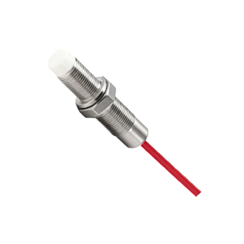
For a PNP-type inductive proximity sensor, the wiring configuration is as follows. Connect the brown wire to the positive terminal of the 24V DC power supply. Connect the blue wire to the negative terminal (0V/common) of the same supply. The black wire, which is the switching output, is connected to one terminal of the load (e.g., relay coil terminal A1). The other terminal of the load (relay coil A2) is then connected back to the negative/common of the power supply. In this configuration, when the sensor detects a target, it switches the output transistor, sourcing positive 24V DC from the brown wire connection out through the black wire to the load, thus completing the circuit to common and energizing the load. This "sourcing" method is widely used in crane PLC systems where the input cards are designed to receive a positive voltage signal.
Detailed NPN (Sinking) Sensor Wiring Diagram
The wiring for an NPN-type sensor, while similar, has a critical difference in the output path. Again, connect the brown wire to +24V DC and the blue wire to 0V/common. However, for the black output wire, connect it directly to one terminal of the load. The other terminal of the load is then connected to the positive terminal of the power supply. In this setup, when activated, the sensor's internal transistor switches, allowing current to flow from the positive supply, through the load, into the black wire, and sink down through the sensor to the common (0V) via the blue wire. This "sinking" configuration is equally common. The choice between PNP and NPN often depends on the design of the existing crane control cabinet and the specifications of the PLC's digital input module.
Integration with Crane Safety and Control Circuits
The true application of these wiring principles is seen in the crane's overall safety circuit. For example, a limit detection system may involve multiple proximity sensors strategically placed at the extreme ends of the bridge and trolley travel. The output from these sensors is typically wired into a safety relay module or a dedicated safety PLC. The wiring diagram would show each sensor's output (black wire) connected to a separate input channel on this safety controller. When any sensor is triggered, indicating an approach to a physical limit, the safety controller executes a programmed response, such as decelerating the drive motor, issuing an alarm, or cutting power to the motion contactor. Proper shielding of cables and separation from high-power motor feeder lines is essential in the diagram notes to prevent electromagnetic interference.
Best Practices for Installation and Troubleshooting
A reliable wiring installation goes beyond the schematic. Always ensure the sensor is correctly rated for the operating voltage (e.g., 10-30V DC). Use stranded, shielded cable