Understanding Capacitive Sensing Fundamentals
Capacitive proximity sensors operate based on the principle of capacitance change. All objects possess a dielectric constant, and when a target enters the sensor's electrostatic field, it alters the capacitance between the sensor electrode and ground. This change is detected by the sensor's internal oscillator circuit. The key parameters influencing sensitivity include the target material's dielectric constant, size, distance, and the sensor's active surface area. Unlike inductive sensors, capacitive variants can detect non-metallic objects such as liquids, plastics, and wood, making them versatile for diverse industrial settings. The core challenge lies in distinguishing the minute capacitance shift caused by the target from environmental noise and parasitic capacitances.
Electrode Design and Configuration
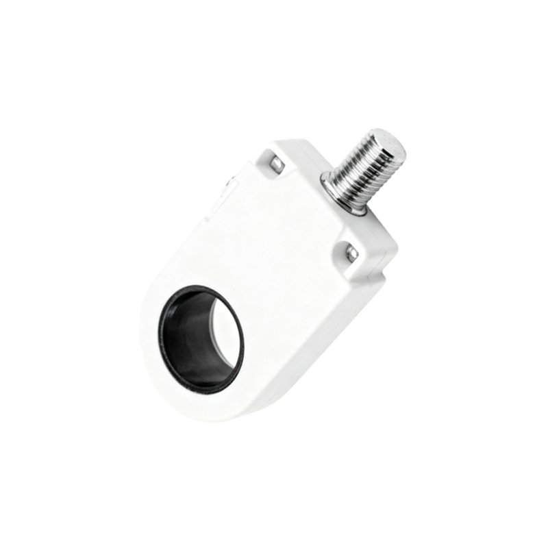
The electrode, often a conductive plate or pattern on a PCB, is the heart of the sensor. Its geometry directly impacts the sensing field's shape and range. A larger electrode area generally increases sensitivity and detection range but may lead to reduced resolution and increased susceptibility to interference. Common configurations include single-electrode (measuring capacitance to ground) and dual-electrode (creating a field between two electrodes) designs. For flush-mount industrial sensors, a guard ring electrode surrounding the active electrode is crucial. This guard ring, driven at the same potential as the sensing electrode, focuses the field forward and minimizes side and rear sensitivity, ensuring stable installation in metal housings. Material choice, typically copper with a protective coating, is vital for durability.
Oscillator and Signal Processing Circuitry
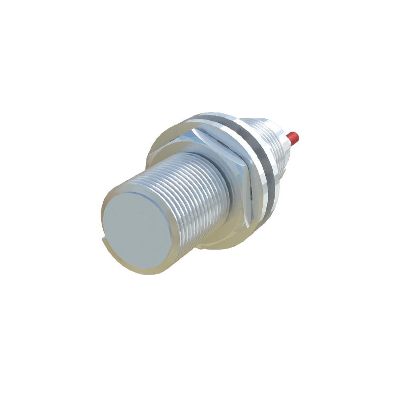
A stable high-frequency oscillator, often in the range of several hundred kHz to a few MHz, charges the sensing electrode. The target's presence alters the resonant frequency or amplitude of this oscillator. Two primary detection methods are employed: amplitude modulation and frequency modulation. The amplitude-based system measures the damping of the oscillator's amplitude, while the frequency-based system tracks the shift in oscillation frequency. The raw signal is then conditioned through amplification and filtering stages. Advanced designs incorporate microcontroller-driven auto-calibration to compensate for environmental drift, such as changes in humidity or temperature, which can affect the dielectric constant of air.
Shielding and Environmental Compensation
Effective shielding is paramount for reliable operation in harsh industrial environments. Electrical noise from motors, variable frequency drives, and other sensors can induce false triggering. Shielding involves a combination of physical metal enclosures, guard electrodes, and careful PCB layout with grounded guard traces. Furthermore, software algorithms play an increasing role. Digital filtering techniques, like moving averages or adaptive thresholds, help reject transient noise. Compensation for material buildup (e.g., dust, condensation) on the sensor face is another critical feature. Some sensors implement a baseline tracking algorithm that slowly adjusts the detection threshold to ignore slow-forming layers while still responding to fast-approaching targets.
Calibration and Sensitivity Adjustment
Calibration determines the sensor's operational point. A potentiometer or teach-in button allows users to set the sensitivity threshold for a specific target at a required sensing distance. The process involves presenting the standard target to the sensor at the nominal distance and adjusting until the output switches. For applications with varying target materials or environmental conditions, sensors with programmable parameters via IO-Link or other digital interfaces offer superior flexibility. These allow remote adjustment of hysteresis, response time, and switching delay, enabling fine-tuning for complex automation tasks without physical access to the sensor.
Application-Specific Design Considerations
Design choices must align with the end application. For liquid level detection in tanks, long-range cylindrical sensors with high sensitivity settings are typical. In packaging machinery detecting plastic bottles, small rectangular sensors with fast response times are preferred. Explosion-proof designs for hazardous areas require intrinsically safe circuits and certified enclosures. The housing material, typically PBT or stainless steel, must withstand chemicals, washdowns, and mechanical impact. The output stage, whether NPN/PNP transistor, analog, or IO-Link, is selected based on the controller interface. Ultimately, rigorous testing under simulated real-world conditions—including temperature cycles, EMC tests, and endurance cycling—validates the design's robustness before deployment.