Proximity sensors are essential components in industrial automation, robotics, and safety systems. Proper installation is critical to ensure accurate detection, reliability, and longevity. This guide provides a comprehensive overview of proximity sensor installation, supported by detailed diagrams and best practices.
Understanding the basic types of proximity sensors is the first step. Inductive sensors detect metallic objects, capacitive sensors sense both metallic and non-metallic materials, and ultrasonic sensors use sound waves for detection. Each type has specific installation requirements.
Installation Diagrams and Key Considerations
1. Mounting Position and Alignment
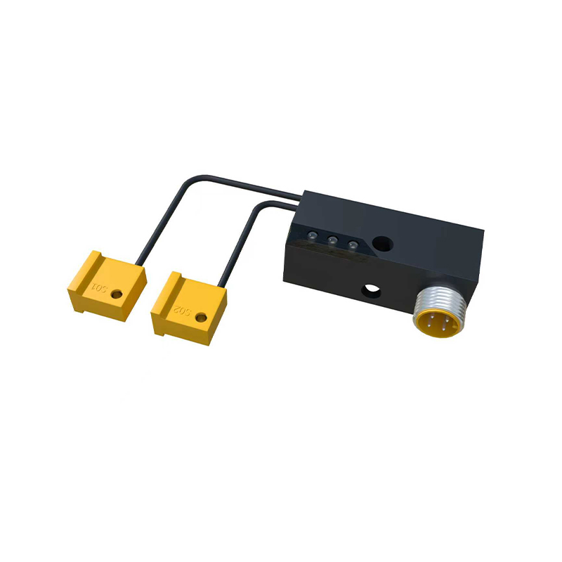
The sensor must be aligned parallel to the target object. Avoid angular misalignment, as it reduces the effective sensing range. For cylindrical sensors, ensure the mounting nut is tightened securely without distorting the housing.
2. Sensing Distance
Maintain a gap between the sensor and the target. The diagram illustrates the nominal sensing distance (Sn), which should typically be 70-80% of the rated distance to account for temperature fluctuations and supply voltage variations.
3. Clearance from Interfering Objects
Metallic objects or other sensors placed too close can cause false triggering. Diagrams show minimum lateral and frontal clearance distances—usually 2-3 times the sensor diameter—to prevent mutual interference.
4. Environmental Protection
For harsh environments, select sensors with appropriate IP ratings. Installation diagrams highlight sealing methods, such as using conduit glands for cable entries and avoiding exposure to excessive dust, moisture, or chemicals.
5. Wiring Connections
Refer to the manufacturer’s wiring diagram. Typically, brown wire connects to DC positive, blue to DC negative, and black (or white) is the output signal. Shielded cables are recommended for noisy electrical environments, with the shield grounded at one end.
Step-by-Step Installation Process
- Step 1: De-energize the system to prevent electrical hazards.
- Step 2: Select the mounting location based on the target material, required sensing range, and environmental conditions.
- Step 3: Secure the sensor using brackets or mounting nuts, ensuring no strain on the cable.
- Step 4: Connect wires according to the diagram, verifying polarity for DC sensors.
- Step 5: Power the system and test detection by moving the target object. Adjust the sensor position if necessary.
Common Installation Errors to Avoid
- Installing sensors too close to moving parts, causing physical damage.
- Ignoring temperature limits, which may lead to drift in sensing characteristics.
- Over-tightening mounting hardware, potentially cracking the sensor housing.
Regular maintenance, such as cleaning the sensing face and checking for loose connections, enhances performance. Always consult the specific sensor’s datasheet for detailed mechanical dimensions and electrical specifications.
Proper installation, guided by accurate diagrams, ensures optimal sensor operation, reduces downtime, and improves system safety. Whether for conveyor systems, machine tools, or automated doors, following these guidelines will lead to reliable and efficient proximity sensing solutions.