Introduction to Hall Effect Sensing
The Hall Effect, discovered by Edwin Hall in 1879, is the fundamental principle behind Hall effect proximity sensors. When a current-carrying conductor is placed in a magnetic field, a voltage, known as the Hall voltage, is generated perpendicular to both the current and the magnetic field. This phenomenon occurs due to the Lorentz force deflecting charge carriers within the material. In modern sensors, this conductor is typically a thin semiconductor element, such as gallium arsenide or indium antimonide, chosen for its high electron mobility and sensitivity. The generated Hall voltage is a linear function of the magnetic flux density, making it an ideal basis for precise, non-contact detection. This core principle enables the creation of robust, solid-state sensors with no moving parts, offering significant advantages in reliability and lifespan over mechanical switches.
Core Components and Sensor Architecture
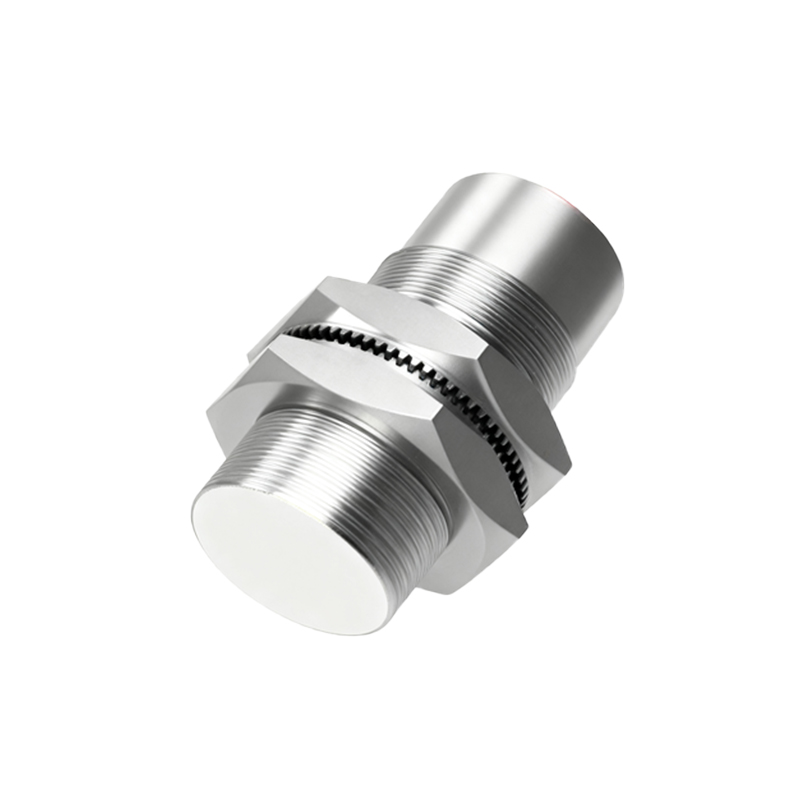
A typical Hall effect proximity sensor comprises several key components integrated into a single package. The primary element is the Hall plate or IC, which contains the semiconductor material where the Hall voltage is generated. This is connected to a signal conditioning circuit, which includes a differential amplifier to boost the tiny millivolt-level Hall signal to a usable voltage. Modern integrated Hall sensors often incorporate additional circuitry such as voltage regulators, Schmitt triggers for hysteresis (to prevent output chatter), and open-collector or push-pull output transistors. The sensor is housed in a protective casing, often made of plastic or metal, with the sensing face positioned to be most receptive to an approaching magnetic field target. The entire assembly is designed to be immune to environmental contaminants like dust, oil, and moisture, which is critical for industrial applications.
Operating Modes: Unipolar, Bipolar, and Latching
Hall effect sensors are categorized by their magnetic response into three main operating modes. Unipolar sensors are activated by a single magnetic south or north pole of sufficient strength and deactivate when the magnetic field is removed. They are simple and common for basic presence detection. Bipolar sensors require both positive (south pole) and negative (north pole) magnetic fields to switch states; one pole turns the output ON, and the opposite pole turns it OFF. This mode offers inherent noise immunity. Latching or bipolar-latching sensors are a specialized type. They require a specific pole to activate (latch ON) and the opposite pole to deactivate (latch OFF). Once switched, they maintain their state even after the magnetic field is removed, making them ideal for pulse counting and position memory applications in brushless DC motors or rotary encoders.
Magnetic Target Interaction and Sensing Distance
The operation of a Hall proximity sensor is defined by its interaction with a magnetic target. The target is typically a permanent magnet, often made from ferrite, neodymium, or samarium cobalt, embedded in or attached to the object to be detected. The sensor does not detect the object itself but the magnetic field it carries. The sensing distance, or operating point, is the distance at which the sensor's output switches state as the target approaches. This distance depends on the strength of the magnet, the sensitivity of the Hall IC, and the magnetic circuit design. Shielding and the orientation of the magnet's poles are critical; a magnet presented with its pole face perpendicular to the sensor face provides the strongest signal. Engineers must carefully select magnet size, grade, and orientation to achieve the required sensing distance in the application.
Output Configurations and Electrical Interface
Hall sensors provide digital or analog output signals to interface with control systems. Digital outputs are either open-collector NPN or sourcing PNP transistor configurations, compatible with PLCs, microcontrollers, and relays. They provide a simple ON/OFF signal. Analog output sensors provide a voltage or current (e.g., 0-10V, 4-20mA) that is proportional to the strength of the magnetic field, enabling precise position measurement. A critical specification is the output's sink or source current capability, which must match the load requirements. Wiring typically involves three or four wires: supply voltage (Vcc), ground (GND), output signal (OUT), and sometimes a separate output for inverse logic. Proper connection with pull-up/pull-down resistors and protection against inductive load kickback and electromagnetic interference (EMI) is essential for stable operation.
Key Advantages in Industrial Applications
Hall effect proximity sensors offer distinct benefits that make them indispensable in automation and machinery. Their solid-state, non-contact nature ensures virtually infinite mechanical life with no wear from physical actuation. They can operate at very high switching frequencies, often in the hundreds of kilohertz range, suitable for high-speed counting and RPM measurement. They are immune to