Introduction to Variable Reluctance Proximity Sensors
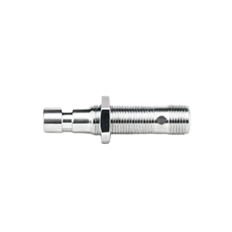
Variable reluctance (VR) proximity sensors are a fundamental type of non-contact sensing device widely used in industrial automation and motion control. Operating on the principle of electromagnetic induction, these sensors detect the presence or absence of ferromagnetic targets, typically iron or steel, without physical contact. The core mechanism involves a permanent magnet and a coil of wire. When a ferromagnetic object enters the sensor's magnetic field, it alters the magnetic reluctance—the opposition to magnetic flux—causing a change in the magnetic circuit. This change induces a voltage pulse in the coil, which is then processed by the sensor's electronics to generate an output signal. Their inherent simplicity and robustness make them a staple in harsh industrial environments where reliability is paramount.
Key Advantages of VR Sensors
The primary strength of variable reluctance sensors lies in their exceptional durability and simplicity. Having no active electronic components at the sensing tip, they are inherently rugged and can withstand extreme temperatures, high vibration, and contaminated environments—common in automotive, aerospace, and heavy machinery applications. They are highly reliable for detecting gear teeth, turbine blades, or other moving ferrous parts, often serving as key components in speed and position monitoring systems like crankshaft or camshaft position sensing in internal combustion engines. Furthermore, VR sensors are self-generating; they produce their own AC voltage signal when a target passes by, eliminating the need for an external power source at the sensing element itself, which simplifies wiring in some configurations. Their output signal amplitude increases with target speed, making them particularly effective for high-speed applications.
Inherent Limitations and Disadvantages
Despite their robustness, VR proximity sensors come with significant limitations. The most notable drawback is their requirement for a moving ferromagnetic target. They cannot detect stationary objects, as a change in magnetic flux is necessary to generate a signal. This also means they have a minimum operating speed; below a certain threshold, the induced voltage is too weak to be detected reliably. The output signal is an analog sine wave whose amplitude and frequency are directly proportional to the target's speed and proximity, requiring additional signal conditioning circuitry (like Schmitt triggers or specialized ICs) to convert it into a clean, digital square wave usable by modern controllers. This adds complexity and cost to the system. Additionally, the sensing distance is generally shorter compared to active electronic sensors like inductive or capacitive types, and they are sensitive to the target's size, material, and speed, requiring careful calibration.
Comparison with Other Proximity Sensor Types
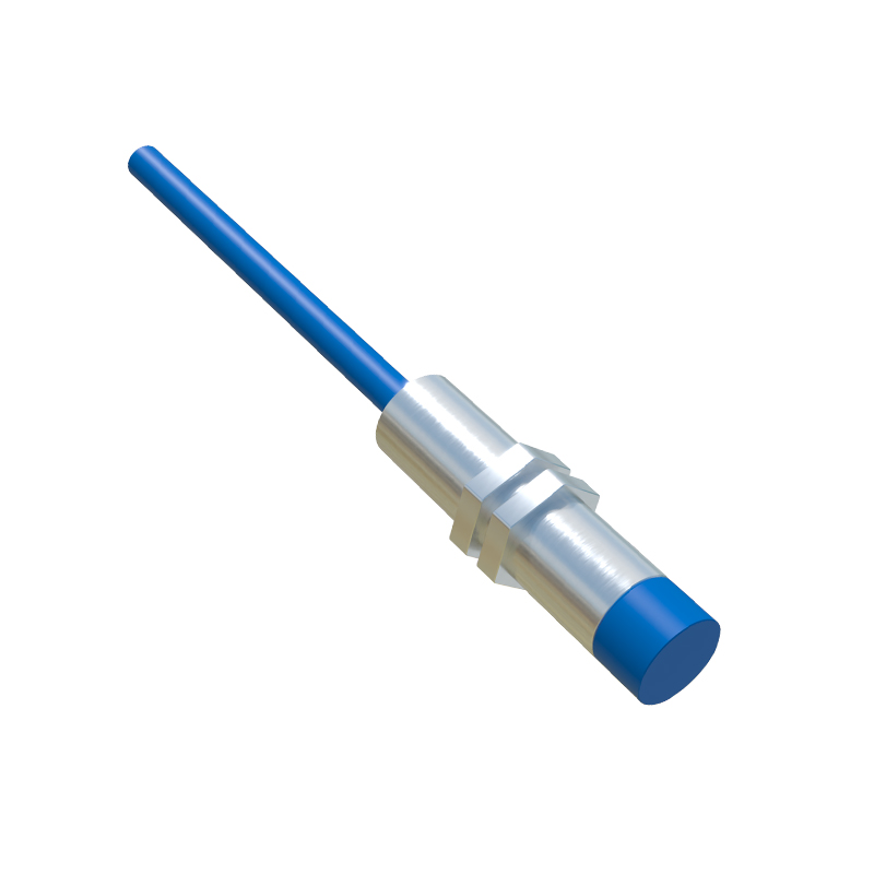
Contrasting VR sensors with other technologies highlights their niche. Active inductive proximity sensors, which contain an oscillator circuit, can detect both stationary and moving ferrous metals with a consistent digital output, but they require continuous power and may be less tolerant of extreme temperatures. Hall-effect sensors, also used for position and speed, provide a digital output from zero speed upwards but require integrated electronics and a magnetic bias. Optical sensors offer long range and can detect non-metallic objects but are vulnerable to dirt and fog. The choice for VR sensors is thus dictated by the application: they are unparalleled for ultra-rugged, high-speed detection of ferrous metals in environments where simplicity and temperature resilience outweigh the need for low-speed operation or static detection.
Typical Industrial Applications
Variable reluctance sensors find their most critical applications in areas demanding utmost reliability under duress. In the automotive industry, they are the traditional choice for crankshaft and camshaft position sensing, vital for engine timing and fuel injection control. In aviation, they monitor turbine engine shaft speed. Industrial uses include speed sensing on gearboxes, conveyors, and rotating machinery, as well as detecting missing teeth on gears for positional reference. They are also employed in anti-lock braking systems (ABS) to measure wheel speed. In each case, the environment is characterized by high temperatures, oil, grease, and metal particulates, conditions where the sensor's passive, solid-state nature provides a significant advantage.
Selection and Implementation Considerations
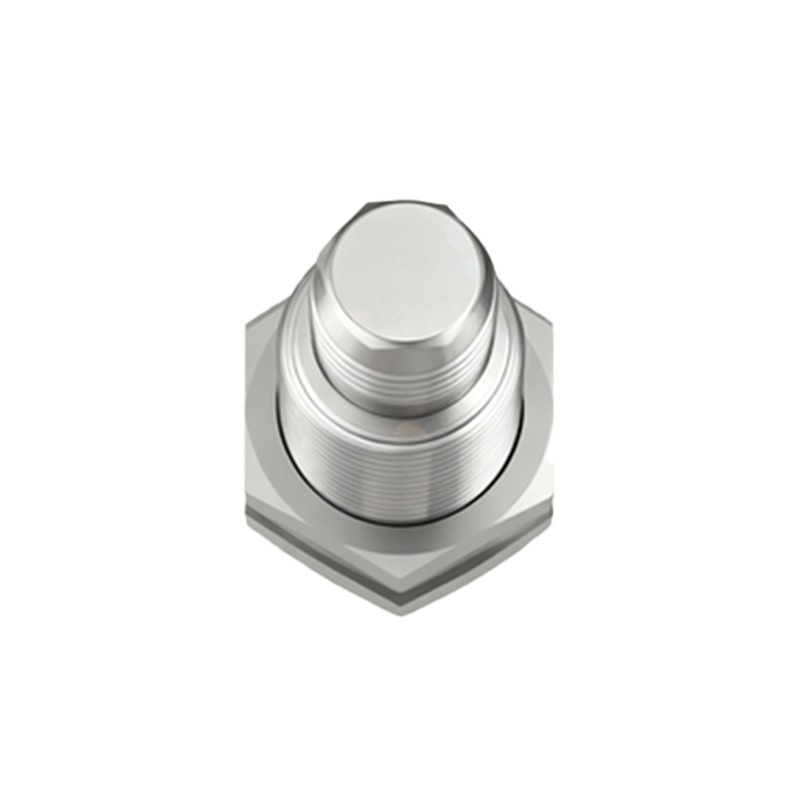
Implementing a VR sensor successfully requires careful system design. Engineers must consider the target material, geometry, and expected speed range. The air gap between the sensor and target is critical and must be maintained within specified limits. Since the output is speed-dependent, the signal conditioning interface must be designed to handle the expected amplitude and frequency range, often incorporating filtering to reject noise. For low-speed applications, a gear tooth sensor with a built-in magnet and integrated signal conditioner may be a more practical hybrid solution. Ultimately, while the sensor itself is simple, the supporting electronics and mechanical mounting are crucial to harnessing its advantages and mitigating its inherent limitations in a modern control system.