Introduction to Photoelectric Sensor Fundamentals
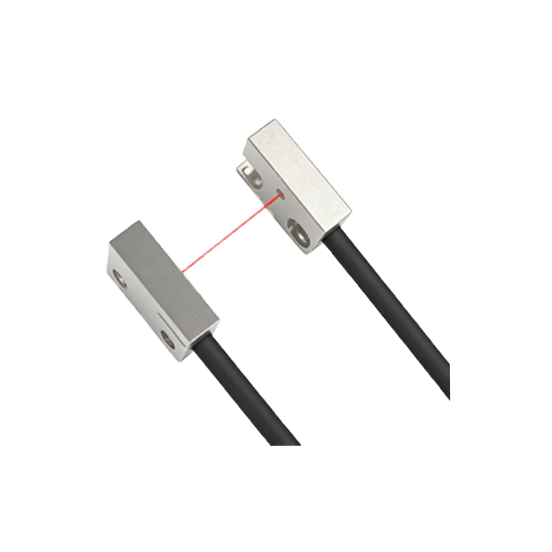
Photoelectric sensors are ubiquitous in industrial automation, playing a critical role in object detection, positioning, and counting. Their operation is based on the detection of light, typically emitted by an internal source and received by a photodetector. The core principle involves the interruption or reflection of this light beam by a target object, which triggers an electrical output signal. Understanding the internal components—the emitter (often an LED), the receiver (a phototransistor or photodiode), and the signal processing circuitry—is the first step toward mastering their external wiring. These sensors are categorized mainly into three types: through-beam (opposed), retro-reflective, and diffuse (proximity) sensors, each with distinct operational and wiring considerations.
Deciphering Sensor Specifications and Datasheets
Before connecting any wire, a thorough review of the sensor's datasheet is non-negotiable. Key electrical specifications dictate the wiring scheme. The operating voltage range (e.g., 10-30 VDC) defines the power supply requirements. The output type is paramount: it can be a transistor output (NPN sinking or PNP sourcing), a relay contact, or an analog output. The load current rating specifies how much current the output can safely switch. Additionally, note the wire color code, which is often standardized: brown for positive DC supply (+V), blue for common negative or 0V, black for the output signal, and white for a second output or control line. Ignoring these details can lead to malfunction or permanent damage.
Standard Wiring Configurations for DC Sensors
For the most common 3-wire DC sensors, wiring follows a logical pattern. For a PNP (sourcing) sensor, connect the brown wire to the positive terminal of your DC power supply. Connect the blue wire to the negative terminal (0V). The black wire is the switched positive output. When the sensor detects an object, it connects the black wire internally to the brown wire's positive supply, "sourcing" current to the load. The load (e.g., a PLC input, relay coil) is then connected between the black wire and the blue wire (0V). For an NPN (sinking) sensor, the brown and blue connections remain the same. However, the black wire becomes a switched negative output. Here, the load must be connected between the positive supply (+V) and the black wire. When activated, the NPN sensor sinks current from the load down to the 0V (blue) line.
Interfacing with Programmable Logic Controllers (PLCs)
Integrating photoelectric sensors with PLCs is a fundamental application. For a PNP sensor connected to a PLC's digital input module, the sensor's black (output) wire goes to the specific PLC input terminal. The PLC input's common point must be connected to 0V (blue). This completes the circuit, allowing the sensor to source current into the PLC input. For an NPN sensor, the PLC input configuration must be compatible. Typically, the PLC input common is connected to +V. The sensor's black wire is connected to the input terminal. When activated, the NPN sensor sinks current from the PLC input, pulling it low. Mismatching PNP sensors with an NPN-configured PLC input (or vice versa) will result in a non-functional circuit. Always verify the PLC input module's sink/source requirements.
Wiring for AC Sensors and Special Functions
Two-wire AC sensors are simpler to wire but have important limitations. They connect in series with the load and the AC power source (e.g., 120VAC). The sensor consumes a small "leakage" current to operate even when off, which must be considered to avoid ghost voltages. Four-wire sensors combine AC power and a separate DC output, offering isolation. Furthermore, sensors with timing functions, teach-in capabilities, or dual outputs (N.O. and N.C.) have additional wires, typically white, gray, or pink. These control wires may require connection to a voltage source or a programming button to set parameters. For these advanced models, the manufacturer's wiring diagram is the ultimate authority.
Shielding, Grounding, and Noise Mitigation
Proper wiring extends beyond making connections; it ensures reliability. In electrically noisy industrial environments, using shielded cables for photoelectric sensors is highly recommended. Connect the cable shield to a stable earth ground at one end only, typically at the control panel, to prevent ground loops. Keep sensor cables away from high-voltage power lines, motor drives, and welding equipment. If using long cable runs, consider voltage drop; using a thicker gauge wire may be necessary to maintain a stable supply voltage at the sensor. Good grounding practices for both the sensor housing (if metal) and the power supply are essential for stable operation and protection against electromagnetic interference (EMI).
Troubleshooting Common Wiring Issues
When a photoelectric sensor fails to operate, a systematic wiring check is the first step. Verify power is present at the sensor terminals with a multimeter. Check for correct polarity for DC sensors. Ensure the load (e.g., PLC input) is functional and correctly connected. For an NPN sensor, confirm the load has a path to positive voltage. For a PNP sensor, confirm the load has a path to ground. A sensor that is constantly "on" might have a wiring short or incorrect load connection. An intermittent signal often points to poor connections, damaged cable insulation, or severe electrical noise. Always isolate and test the sensor independently with a known-good load, like a pilot light, to confirm its basic function before blaming complex control logic.