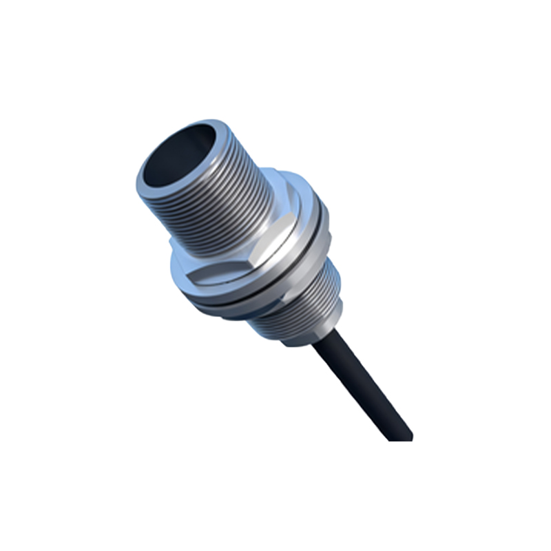
Square proximity sensors are widely used in industrial automation for detecting the presence or absence of objects without physical contact. Proper wiring is crucial to ensure reliable operation and prevent damage to the sensor or connected equipment. This guide provides a step-by-step overview of wiring square proximity sensors, covering common types, connection methods, and best practices.
Most square proximity sensors feature a standardized wiring configuration, typically involving three or four wires. The three-wire sensors include a brown wire for positive voltage supply (often +24V DC), a blue wire for negative or ground connection, and a black wire as the output signal. Four-wire sensors add an additional output, usually white or gray, for complementary signaling. Always refer to the manufacturer’s datasheet for specific wire colors and functions, as variations exist between brands.
To wire a square proximity sensor, first de-energize the power source to ensure safety. Identify the sensor’s operating voltage—common ranges are 10-30V DC or 90-250V AC. Connect the brown wire to the positive terminal of the power supply and the blue wire to the negative terminal. For AC sensors, polarity may not apply, but follow the manufacturer’s instructions. The output wire (black) should be connected to the load, such as a programmable logic controller (PLC) input, relay, or indicator. If using a four-wire sensor, connect the second output as needed for normally open or normally closed operations.
Shielded cables are recommended for environments with electrical noise, such as factories with motors or frequency drives. Ground the shield at one end to prevent ground loops. Maintain proper cable management by avoiding sharp bends and keeping wires away from high-voltage lines. Ensure connections are secure using crimp terminals or screw terminals, as loose wiring can cause intermittent failures.
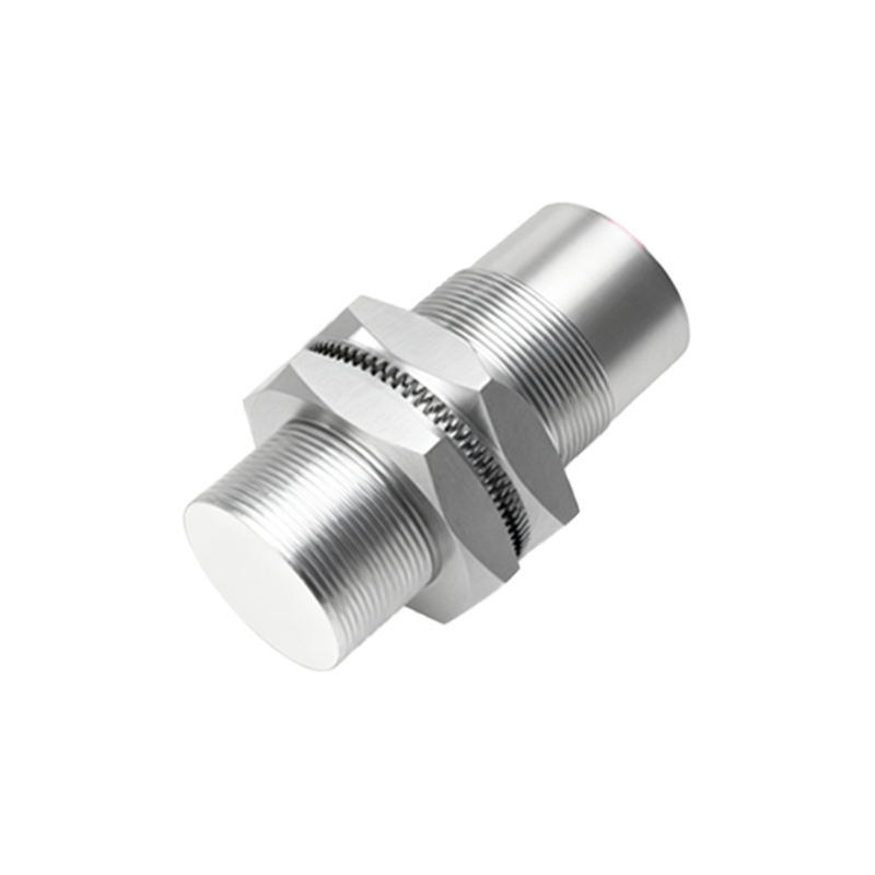
Testing is essential after wiring. Apply power and verify the sensor’s indicator LED activates when an object enters its detection range. Use a multimeter to check output voltage or current signals. For inductive sensors, ensure the target material (e.g., metal) is within the specified sensing distance. Capacitive sensors may require calibration for non-metallic objects.
Common wiring mistakes include incorrect voltage application, reversed polarity for DC sensors, or overloading the output. Exceeding the sensor’s current rating can lead to premature failure. Additionally, avoid installing sensors near reflective surfaces or other electromagnetic sources that could cause false triggers. For harsh environments, choose sensors with appropriate ingress protection (IP) ratings and use conduit or protective casings.
In summary, wiring square proximity sensors involves understanding wire functions, matching voltage requirements, and implementing noise reduction measures. Regular maintenance, such as cleaning sensor faces and inspecting connections, prolongs lifespan and ensures consistent performance. By following these guidelines, users can achieve efficient and safe integration into automated systems.