Understanding Photoelectric Sensing Technology
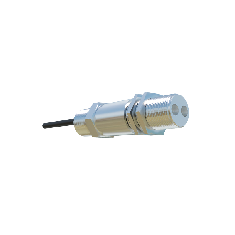
Photoelectric sensors operate by emitting a beam of light, typically infrared, visible red, or laser, and detecting changes in the received light intensity. These sensors consist of a transmitter and a receiver. In reflective models, the emitter and receiver are housed together; the light beam reflects off a surface back to the receiver. In through-beam setups, the emitter and receiver are separate units facing each other, with the object breaking the beam. For line following, diffuse reflective sensors are most common. They detect the contrast between a line (often black) and the background (often white) by measuring the amount of light reflected. The high precision and fast response time of photoelectric sensors make them ideal for dynamic automated guidance applications.
Core Principles of Line Following
The fundamental task involves a vehicle or robotic platform autonomously tracking a predefined path. This path is usually a line with a distinct color that contrasts sharply with the surrounding surface. The photoelectric sensor, mounted on the vehicle's underside, continuously scans the area directly beneath it. When the sensor is over the high-reflectivity background (e.g., white), a large portion of the emitted light is reflected back to the receiver, generating a strong signal. When it moves over the low-reflectivity line (e.g., black), significantly less light is reflected, causing a detectable drop in the receiver's output signal. This binary or analog signal variation is the primary input for the control system.
System Configuration and Sensor Arrangement
Effective line following requires careful sensor selection and placement. A single sensor can provide basic tracking but is prone to losing the line on curves. Therefore, arrays of multiple sensors are standard in industrial applications. A common configuration uses three to five sensors aligned perpendicular to the direction of travel. This array creates a "view" of the line's position relative to the vehicle's center. The central sensor acts as the primary tracker when on the line. The outer sensors detect when the vehicle begins to drift left or right. The spacing between sensors and their height above the surface are critical parameters that must be calibrated based on line width and required tracking precision.
Signal Processing and Control Logic
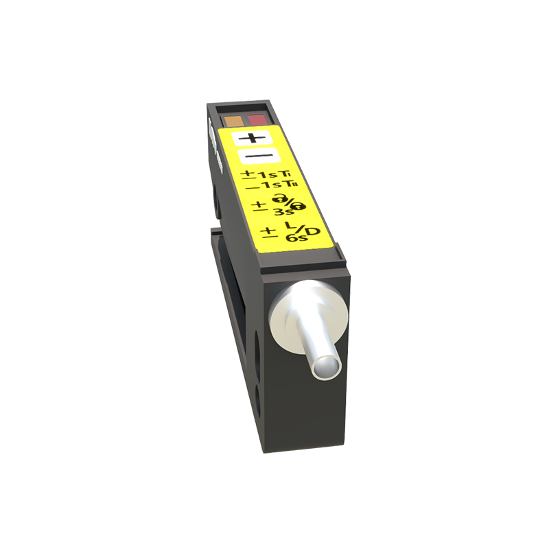
The raw analog signals from the sensor array are converted into digital data or directly processed by a microcontroller or PLC (Programmable Logic Controller). The control logic interprets the pattern of sensor activation. For instance, if only the leftmost sensor detects the black line, the logic determines the vehicle is too far to the right and sends a correction command to steer left. More advanced systems use proportional-integral-derivative (PID) control algorithms. These algorithms use the magnitude of error (e.g., how far from center the line is detected) to calculate smooth, precise steering adjustments, minimizing overshoot and oscillation for stable, high-speed tracking.
Environmental Considerations and Calibration
Performance can be affected by ambient light, surface texture, and dust. Industrial-grade photoelectric sensors often feature modulated light signals and specialized filters to reject ambient light interference. Regular calibration is essential. This involves setting thresholds to distinguish reliably between the line and the background under current lighting conditions. Some systems perform auto-calibration at startup. Maintaining a consistent contrast ratio between the line and the background is paramount; therefore, line tape or paint must be chosen for its durable, non-reflective properties, and the working environment should have controlled, uniform illumination where possible.
Applications in Industrial Automation
Photoelectric line following is ubiquitous in automated guided vehicles (AGVs) and autonomous mobile robots (AMRs) within warehouses, factories, and distribution centers. These systems transport materials along flexible routes defined by simple floor tape, eliminating the need for fixed tracks or magnetic guides. They are also employed in automated assembly lines, where robotic carts follow precise paths, and in printing or packaging machinery for web guidance, ensuring material flows in correct alignment. The reliability, non-contact nature, and cost-effectiveness of photoelectric sensors make them a cornerstone of modern, flexible automation.
Advancements and Integration with Other Technologies
While fundamental principles remain, integration with other sensing modalities enhances robustness. Some systems combine photoelectric sensors with inertial measurement units (IMUs) or odometry encoders to maintain position during momentary line loss or at intersections. Machine vision cameras are sometimes used for higher-level path decision-making, while photoelectric sensors handle the continuous, high-frequency tracking. Furthermore, developments in smart sensors with integrated logic and industrial networking protocols (like IO-Link) allow for easier configuration, diagnostics, and real-time parameter adjustment from a central control system, pushing the capabilities of line-following systems further.