Introduction to Inductive Proximity Switches
Inductive proximity switches, often referred to as proximity sensors or proximity switches, are fundamental components in modern industrial automation. These non-contact electronic devices detect the presence or absence of metallic objects without any physical contact. Operating on the principle of electromagnetic induction, they generate an oscillating electromagnetic field from a coil located at the sensing face. When a metallic target enters this field, eddy currents are induced within the target, causing a change in the oscillation amplitude. This change is detected by the sensor's internal circuitry, which subsequently triggers a solid-state output signal. The key advantage lies in their robustness, high switching frequency, and immunity to environmental factors like dust, oil, and moisture, making them ideal for harsh manufacturing environments such as assembly lines, machine tools, and material handling systems.
Core Operating Principle and Design
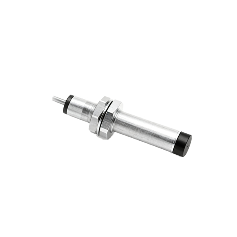
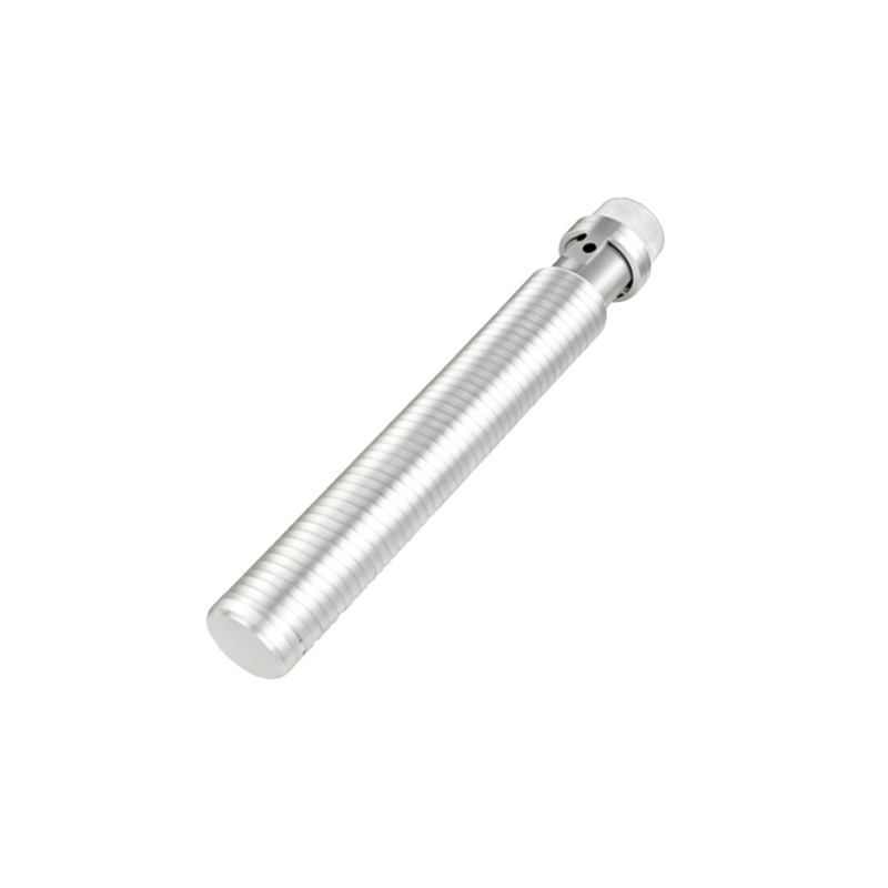
The heart of an inductive proximity switch is its oscillator, coil, and evaluation circuit, typically housed in a robust, threaded cylindrical metal or polymer body. The oscillator generates a high-frequency electromagnetic field that radiates from the active face of the sensor. For a standard shielded (flush-mountable) type, the field is concentrated directly in front, allowing installation flush with a metal bracket without false triggering. Unshielded (non-flush) types have a more extended sensing field and require a clear surrounding area. The sensing distance, or nominal range (Sn), is a critical specification, typically ranging from 1 to 40 mm for standard models, and is defined for a standard target of mild steel. Factors like target material, size, and shape influence the effective sensing distance; for instance, stainless steel may reduce the range, while copper or aluminum reduces it further. The output is usually a solid-state PNP or NPN transistor, or a two-wire AC/DC version, providing a reliable switch signal to a PLC or controller.
Key Specifications and Selection Criteria
Selecting the correct inductive proximity switch requires careful analysis of several parameters. The sensing distance must be chosen with a safety margin, typically 70-80% of the nominal range, to account for mechanical tolerances and temperature drift. The housing material and IP (Ingress Protection) rating are vital for durability; an IP67 rating is common for washdown and outdoor conditions. Electrical characteristics include operating voltage (e.g., 10-30 VDC, or 20-250 VAC), output current, and switching frequency (how many on/off cycles per second). Engineers must also consider the target material's influence factor, temperature range, and connection type (pre-wired cable or quick-disconnect). For specialized applications, variants like analog output sensors (providing a continuous signal proportional to distance), high-temperature models, or weld-field immune types are available to resist interference from welding currents.
Installation, Wiring, and Configuration Practices
Proper installation is crucial for reliable operation. The sensor must be mounted securely to minimize vibration effects. For flush-mountable sensors, ensure the surrounding metal is non-ferrous or maintain the recommended clearance to prevent shielding effects. Wiring must follow the manufacturer's diagram precisely. For a 3-wire DC sensor, the brown wire is typically connected to positive voltage (+V), the blue wire to common negative (0V), and the black wire is the switched output. A load (like a PLC input) is connected between the output and the opposite supply rail. It is essential to include protective devices such as surge suppressors for inductive loads. Configuration often involves setting the sensitivity or hysteresis, if adjustable, to prevent chatter in unstable conditions. Regular maintenance involves checking for physical damage, buildup of metallic debris on the sensing face, and verifying the output signal under operational conditions.
Common Applications Across Industries
Inductive proximity switches are ubiquitous in automation. In automotive manufacturing, they count parts, detect piston position in cylinders, and confirm the presence of metal components on pallets. In packaging machinery, they monitor fill levels of metallic containers or detect the position of capping heads. On CNC machine tools, they serve as homing and limit switches for axis movement. In material handling, they detect the position of metal rollers, chains, or grippers. A specific and critical application is in safety systems, where they are used as non-contact interlock switches on guards and doors to ensure machinery stops when access is granted. Their ability to function in dirty, oily, or wet conditions where optical sensors would fail makes them the default choice for many heavy-industry position-sensing tasks.
Troubleshooting and Diagnostic Tips
When an inductive proximity switch malfunctions, a systematic approach is required. First, verify the power