Understanding Liquid Level Proximity Sensor Types
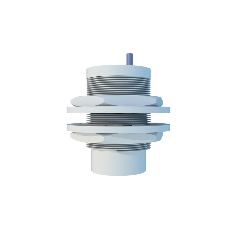
Before beginning any wiring procedure, it is crucial to identify the type of liquid level proximity sensor you are working with. The two primary categories are inductive and capacitive sensors. Inductive sensors are typically used for detecting metallic tanks or conductive liquids, generating an electromagnetic field. Capacitive sensors, on the other hand, can detect both conductive and non-conductive liquids by measuring changes in capacitance. Additionally, sensors come in various output configurations: NPN (sinking), PNP (sourcing), or analog (4-20mA or 0-10V). The wiring process differs significantly based on these types and outputs. Always consult the manufacturer's datasheet for the specific model to confirm its electrical characteristics, voltage ratings, and output type. This initial step prevents damage to the sensor and connected control systems.
Essential Tools and Safety Precautions
Gather all necessary tools and materials before starting. You will typically need a screwdriver, wire strippers, electrical tape or heat-shrink tubing, and appropriate gauge wires. The most critical step is ensuring complete power isolation. Disconnect all power sources to the control panel, PLC, or power supply. Verify the absence of voltage using a multimeter. Wear appropriate personal protective equipment (PPE) such as insulated gloves and safety glasses. Work in a dry environment to prevent short circuits, especially when dealing with liquid detection applications. Plan the cable routing to avoid sharp edges, high-temperature zones, or areas with excessive vibration that could compromise the wiring integrity over time.
Wiring a Standard 3-Wire DC Sensor
The three-wire DC sensor is the most common configuration. It consists of three distinct wires: brown (or red) for positive supply voltage (+V), blue (or black) for negative/common (0V), and black (or white) for the output signal. First, connect the brown wire to the positive terminal of your DC power supply, typically 10-30V DC. Connect the blue wire to the negative terminal of the same power supply. The black output wire is then connected to the load. For a PNP (sourcing) sensor, the output provides positive voltage; connect the black wire to the input of your PLC, relay, or indicator lamp, and connect the other side of that load back to the power supply's negative. For an NPN (sinking) sensor, the output connects to ground; wire the load between the positive supply and the sensor's black output wire.
Connecting to a Programmable Logic Controller (PLC)
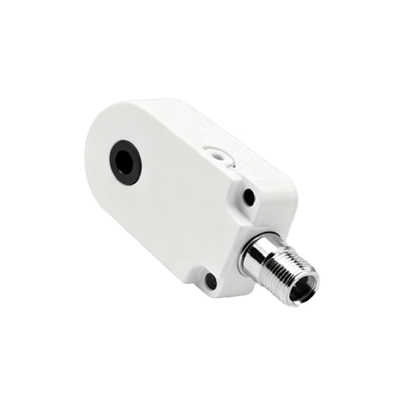
Integrating a proximity sensor with a PLC requires careful attention to the PLC input module type. First, identify if your PLC digital input card is configured for sinking or sourcing input. Match this with your sensor's output type (NPN or PNP) to ensure compatibility. For a PNP sensor connected to a sinking-input PLC card, wire the sensor's output (black) to the designated PLC input terminal (e.g., I0.0). The common terminal of that input group on the PLC card must be connected to the negative side of the power supply. Shielded cable is highly recommended for this connection to minimize electrical noise interference. Terminate the cable shield at the ground terminal on the PLC rack, ensuring it is grounded at only one end to prevent ground loops.
Wiring for Analog Output and 2-Wire Sensors
For analog output sensors (e.g., 4-20mA), the wiring is simpler but requires precise calibration. These sensors usually have two wires: power and signal are combined. Connect one wire to the positive terminal of the DC power supply (often 12-24V DC). Connect the other wire to the positive input terminal of your analog input device (like a PLC analog card or a display). The negative terminal of the analog input device is then connected back to the negative terminal of the power supply, completing the loop. The current signal (4-20mA) proportional to the liquid level flows through this loop. For older 2-wire AC sensors, the sensor is wired in series with the load and the AC power source, similar to a switch; extreme caution is needed due to the live AC voltage.
Testing and Commissioning the Installation
After all connections are secure and double-checked, you can proceed to apply power. First, power up the system without introducing the target liquid. Observe the sensor's status LED (if equipped). Many sensors have a LED that indicates power and output state. Using a multimeter, measure the voltage or current at the output terminal under "empty" conditions to verify it matches the datasheet (e.g., 0V for