Introduction to Proximity Sensing Technology
Proximity sensors are fundamental components in modern electrical engineering and industrial automation. These devices detect the presence or absence of an object within a specific range without any physical contact. The core principle relies on altering a field or emitting a signal beam. When a target object enters this field, it causes a change in the signal's state. This change is then converted by the sensor's electronics into an electrical output signal, typically a switch closure or a change in output current. The absence of mechanical contact and the sensor's few moving parts result in long operational life and high reliability. This makes them ideal for harsh environments where dirt, oil, or vibration would compromise limit switches or other mechanical detection methods.
Core Operating Principles and Types
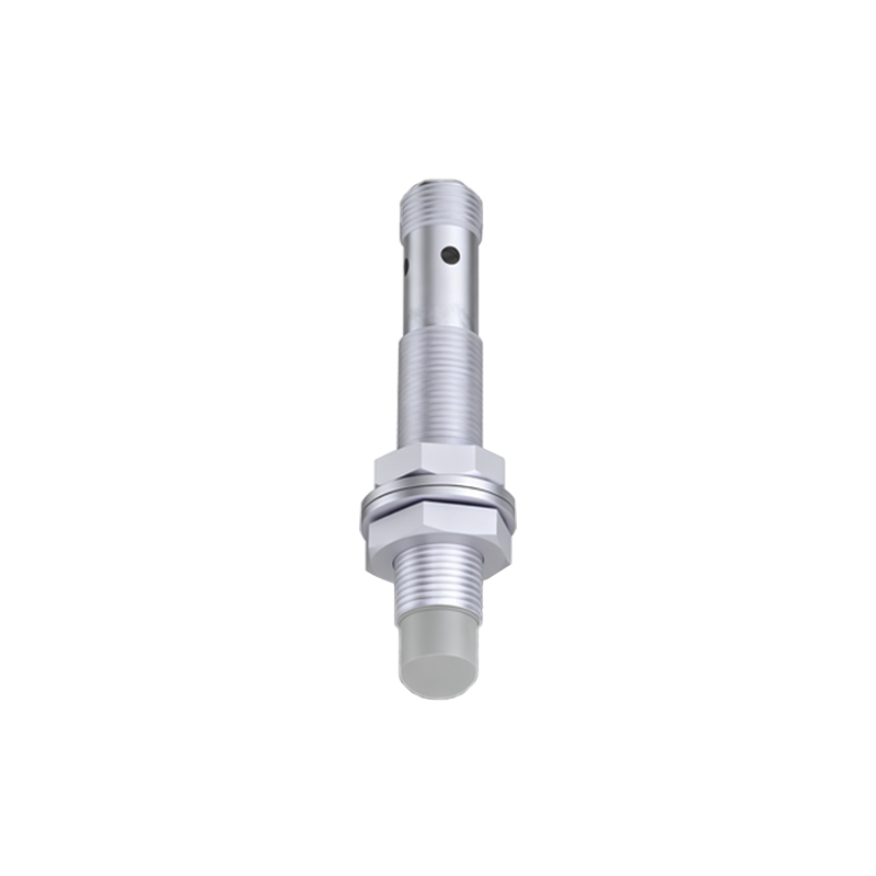
The functionality of a proximity sensor is defined by its underlying technology. The most common types are inductive, capacitive, ultrasonic, and photoelectric sensors. Inductive proximity sensors generate an oscillating electromagnetic field. They are used exclusively for detecting metallic objects. When a metal target enters this field, eddy currents are induced on the metal's surface. These currents absorb energy from the oscillator, causing the oscillation amplitude to decrease. This decrease triggers a detection circuit which changes the sensor's output state. Capacitive sensors, in contrast, can detect both metallic and non-metallic materials like liquids, plastics, or wood. They work by generating an electrostatic field. Any object that enters this field changes its capacitance, which is measured by the sensor's circuitry to determine presence.
Inductive Sensor Detailed Operation
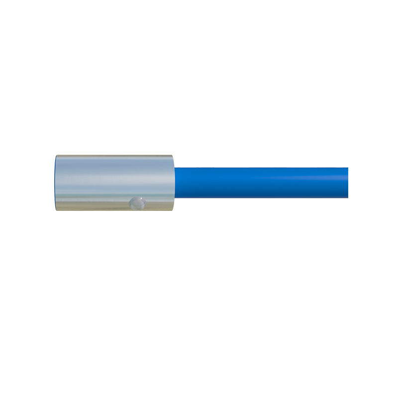
An inductive proximity sensor's operation is a precise electromagnetic process. The key component is a coil wound around a ferrite core, connected to an oscillator. The oscillator creates a high-frequency alternating magnetic field that radiates from the sensor's active face. In the absence of a metal target, the oscillator runs at a constant amplitude. As a conductive metal object approaches, the alternating magnetic field induces circulating currents (eddy currents) within the target. These eddy currents create their own magnetic field, which opposes the original field from the sensor. This opposition acts as a load, damping the oscillator's energy and reducing its amplitude. A threshold circuit monitors this amplitude. Once the damping reaches a preset threshold—corresponding to a specific sensing distance—the circuit triggers, switching the solid-state output (usually NPN or PNP). The sensor is insensitive to non-conductive materials, making it highly selective.
Capacitive Sensor Detailed Operation
Capacitive proximity sensors operate on the principle of capacitance change. The sensor face acts as one plate of a capacitor, with the ground plane or a surrounding shield acting as the other. The oscillator circuit is connected to this capacitive system. When no target is present, the sensor has a baseline capacitance. When any object with a dielectric constant different from air (virtually all materials) enters the electrostatic field, it effectively becomes the dielectric of the capacitor, increasing the overall capacitance. The sensor's circuit is tuned to oscillate at a specific frequency related to this capacitance. The intruding object changes the capacitance, which in turn changes the oscillation frequency or amplitude. A demodulator circuit detects this change and triggers the output switch when the shift exceeds a calibrated level. Sensitivity adjustments allow these sensors to ignore certain materials or detect materials through thin non-metallic barriers.
Output Configuration and Wiring
The electrical output of a proximity sensor is crucial for integration into control systems. Most modern sensors provide a solid-state DC output, categorized as either NPN (sinking) or PNP (sourcing). In a PNP configuration, the sensor switches the positive voltage line to the load. In an NPN configuration, it switches the negative or ground line. The choice depends on the PLC or controller input card requirements. Typically, a three-wire design is standard: brown wire for DC+, blue wire for DC-, and black wire for the switched output signal. Some sensors also feature analog outputs (4-20 mA or 0-10V) proportional to the distance to the target, known as analog proximity sensors. Others offer IO-Link digital communication for advanced diagnostics and parameter setting. Proper shielding and wiring practices are essential to prevent electrical noise from causing false triggers.
Key Application Considerations
Selecting and applying a proximity sensor requires careful analysis of several parameters. The rated sensing distance (Sn) is specified for a standard target. Real-world sensing distance can be affected by the target material's properties, size, and shape. For inductive sensors, a correction factor is applied for different metals; steel is the reference (factor 1.0), while aluminum or copper may reduce the effective range. Mounting is another critical factor; flush-mountable sensors can be embedded in metal without