Understanding Proximity Sensor Fundamentals
Proximity sensors are non-contact electronic devices designed to detect the presence or absence of an object within a specified sensing range. They operate on various principles, including inductive, capacitive, and photoelectric sensing. Inductive sensors detect metallic objects, capacitive sensors detect both metallic and non-metallic materials, and photoelectric sensors use light beams. The core function remains the same: to provide a reliable switching signal without physical contact. This characteristic makes them ideal for harsh industrial environments where durability, speed, and reliability are paramount. Before examining the wiring, it is crucial to identify the sensor type (e.g., NPN or PNP, normally open or normally closed) and its voltage rating, as these specifications directly dictate the correct wiring configuration.
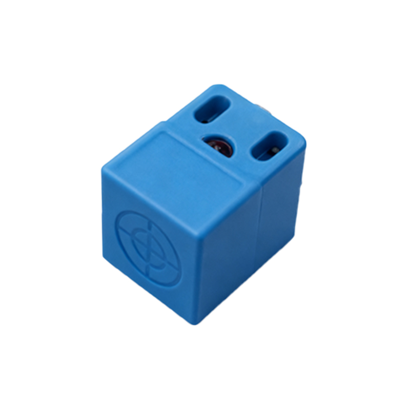
Key Components and Terminal Identification
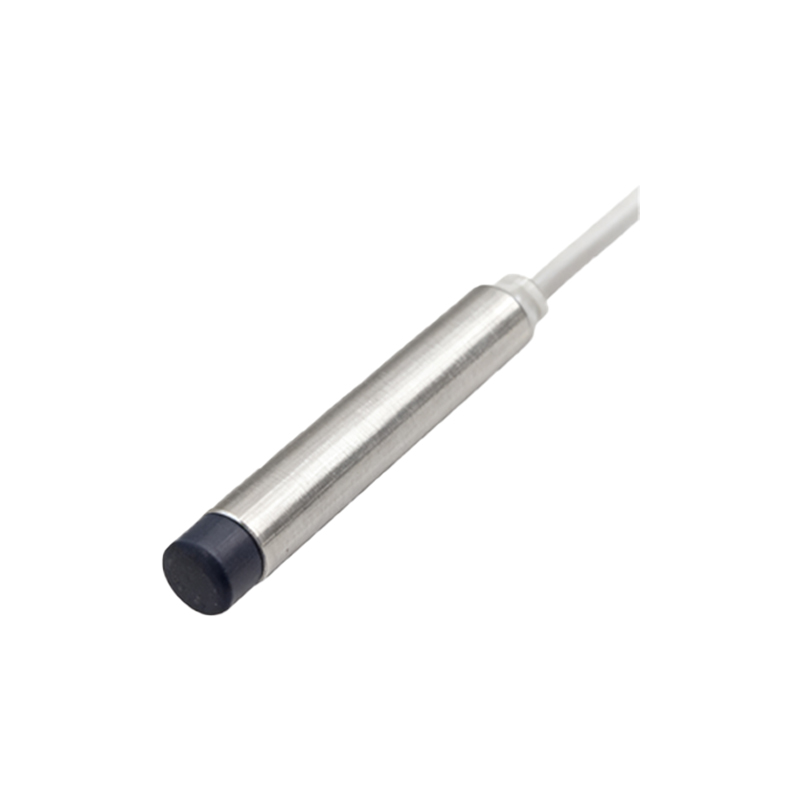
A standard three-wire DC proximity sensor typically features three distinct terminals, often labeled or color-coded. The universal color code is brown for the positive supply voltage (V+), blue for the common negative or 0V (V-), and black for the output signal wire. Some sensors may also have a white wire for a complementary output or diagnostic function. The sensor's housing or datasheet will clearly indicate these terminals. Additionally, a two-wire AC/DC sensor will have only two terminals, integrating the supply and load circuit. Proper identification is the first and most critical step to prevent damage to the sensor or the connected control system, such as a Programmable Logic Controller (PLC) input module or a relay.
Wiring an NPN Sinking Proximity Sensor
An NPN sensor is a sinking device, meaning it switches the negative or 0V line to the load. In a typical 24VDC system, connect the brown wire to the positive DC supply (+24V). Connect the blue wire to the common negative (0V) of the power supply. The black output wire is connected to the load (e.g., one side of a PLC digital input). The other side of the PLC input is then connected to the positive supply (+24V). When the sensor detects a target, the NPN transistor activates, sinking current from the PLC input to 0V, thereby completing the circuit and signaling the PLC. This configuration is common in European and Asian markets.
Wiring a PNP Sourcing Proximity Sensor
A PNP sensor is a sourcing device, meaning it switches the positive voltage line to the load. The power connections remain identical: brown to +24V and blue to 0V. The critical difference lies in the output connection. The black output wire from the sensor is connected to the load (PLC input). The other side of the PLC input is now connected to the common negative (0V). When activated, the PNP transistor sources current from the +24V supply through the sensor's output to the PLC input, creating a voltage signal at the input terminal. This wiring scheme is frequently preferred in North America. Mismatching NPN and PNP wiring will result in a non-functional circuit.
Connecting to a PLC Digital Input Module
Integration with a PLC is a standard application. For a DC input module, first verify if the module is designed for sinking (common positive) or sourcing (common negative) inputs. This determines compatibility with NPN or PNP sensors. For a sinking input module (common +24V), use a PNP sensor. The sensor's black wire connects to the specific input terminal, and the module's common is tied to +24V. For a sourcing input module (common 0V), use an NPN sensor. Here, the sensor's black wire connects to the input terminal, and the module's common is connected to 0V. Always ensure the voltage ratings of the sensor and PLC module match to avoid hardware damage.
Two-Wire AC Proximity Sensor Wiring
Two-wire sensors are simpler but require careful consideration of the load. They connect in series with the power supply and the load, similar to a mechanical switch. For an AC sensor, one wire connects to the live (L) AC voltage, and the other wire connects to one terminal of the load (like a relay coil). The other terminal of the load connects to the neutral (N) line. A critical factor is the residual current or leakage current present even when the sensor is off. This current must be lower than the minimum holding current of the load to prevent unintended activation. Using a shunt resistor in parallel with the load is often necessary to bypass this leakage current.
Shielded Cable and Noise Immunity Practices
In electrically noisy industrial environments, proper shielding is essential for stable sensor operation.