Understanding the Fundamentals of Proximity and Photoelectric Sensing
Proximity and photoelectric sensors are indispensable components in modern industrial automation, serving as the "eyes" of a system. While both detect the presence or absence of objects without physical contact, their operating principles differ significantly. Inductive proximity sensors generate an electromagnetic field to detect metallic objects. Capacitive variants detect any material by sensing changes in capacitance. Photoelectric sensors, on the other hand, utilize a light beam—typically infrared, visible red, or laser. The three main types are through-beam (separate emitter and receiver), retro-reflective (bounces light off a reflector), and diffuse (reflects light directly off the target). Successful adjustment begins with selecting the correct sensor type for the application, considering factors like target material, size, required sensing distance, and environmental conditions such as dust, moisture, or ambient light.
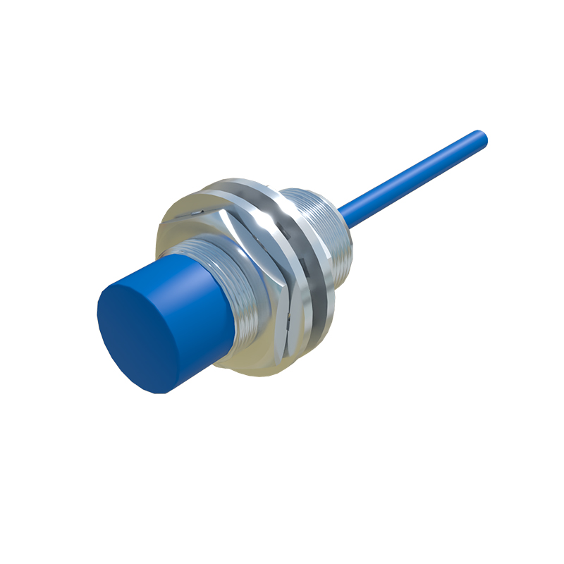
Initial Installation and Alignment Procedures
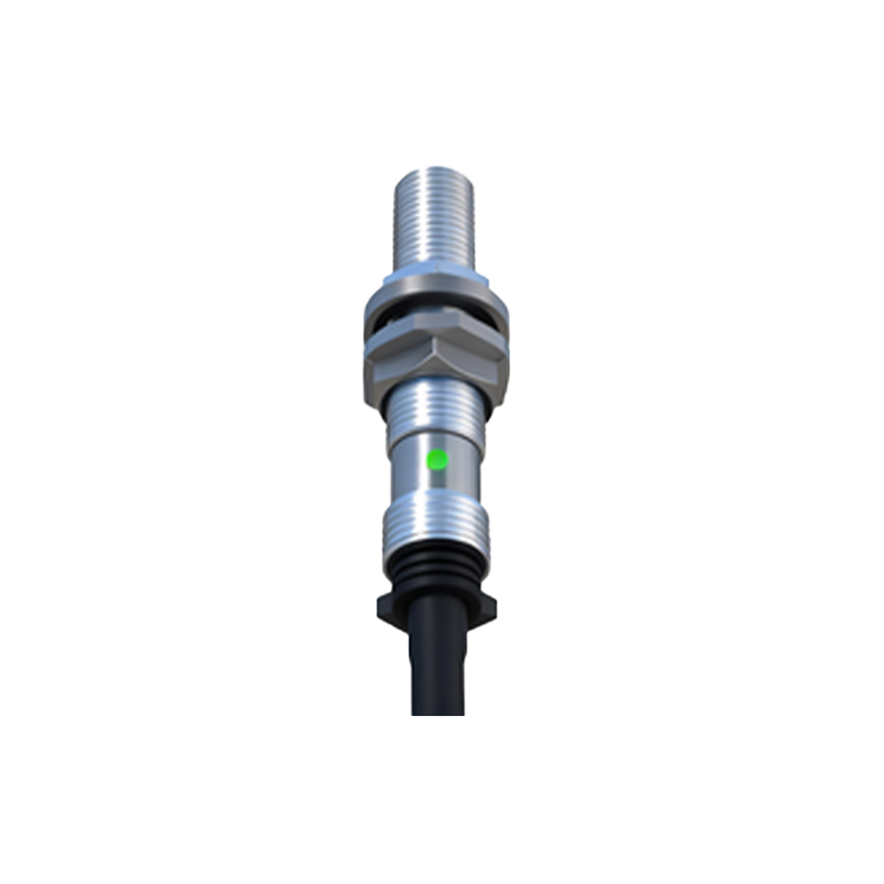
Proper mechanical installation is the critical first step. Securely mount the sensor using appropriate brackets to minimize vibration. For photoelectric sensors, precise optical alignment is paramount. For through-beam systems, carefully align the emitter and receiver lenses. Use the sensor's built-in alignment indicator, often an LED that changes state or brightness when alignment is optimal. For retro-reflective sensors, ensure the reflector is clean and squarely aligned to the sensor beam. Avoid mounting sensors facing highly reflective backgrounds or direct sunlight, which can cause false triggering. Position the sensor so the target will pass through the most sensitive area of its sensing field or beam. Always refer to the manufacturer's datasheet for specific mounting distances and recommended setups to ensure reliable operation within the specified sensing range.
Utilizing Sensitivity Adjustments and Threshold Setting
Most proximity and photoelectric sensors feature a sensitivity potentiometer or digital configuration options. This adjustment controls the threshold at which the sensor's output switches. For a photoelectric sensor, turning the potentiometer clockwise typically increases sensitivity, allowing it to detect smaller, less reflective, or more distant objects. However, excessive sensitivity can lead to instability, causing the sensor to trigger on background objects, dust, or ambient light. The goal is to set the sensitivity just high enough to reliably detect the target under all operating conditions, while providing a safety margin. A best practice is to introduce the target, increase sensitivity until the sensor triggers, then further increase it by 10-15% to account for environmental variations. For proximity sensors, sensitivity adjustment may be used to tune out non-target metals or adjust for specific target sizes.
Fine-Tuning with Timing Functions and Response Control
Modern sensors often include configurable timing functions crucial for stable operation in dynamic applications. These include ON-Delay, OFF-Delay, and One-Shot timers. An ON-Delay timer can be used to confirm a target's presence is stable before triggering an output, effectively filtering out brief interruptions like passing debris. An OFF-Delay holds the output signal for a set time after the target leaves, useful in processes like sealing or filling. The One-Shot timer generates a fixed-duration output pulse regardless of how long the target is present, ideal for counting or triggering subsequent actions. Additionally, many sensors offer a response frequency setting. Setting this too high for a slow-moving application can make the sensor overly responsive to electrical noise, while setting it too low in a high-speed application may cause missed detections. Match the response time to the speed of your process.
Implementing Effective Background Suppression Techniques
A common challenge, especially for diffuse photoelectric sensors, is distinguishing the target from the background. Advanced sensors offer background suppression functionality, either through triangulation-based methods or adjustable sensing windows. This allows the sensor to ignore objects beyond a programmed distance. To adjust, place the actual target at the desired maximum sensing distance and adjust the "far" limit until the sensor just triggers. Then, place an object representing the background (e.g., a conveyor belt or machine part) just beyond that point and verify the sensor does not trigger. For proximity sensors operating near metallic backgrounds, many models feature a built-in "shielded" design or allow for a reduced sensing range setting to prevent interference from adjacent machinery or mounting brackets.
Diagnosing Issues and Performing Routine Verification
Even after perfect adjustment, sensors can drift due to temperature changes, lens contamination, or component aging. Establish a routine verification schedule. Use the sensor's status LED as a primary diagnostic tool: a steady light often indicates power, a blinking light may indicate a fault or output activation, and a change in color can signal alignment or overload conditions. For photoelectric sensors, keep lenses clean using only approved cleaners. Monitor the operating margin or "excess gain." Many sensors have a teach-in function to