Introduction to Photoelectric Sensor Wiring
Photoelectric sensors are widely used in industrial automation for detecting objects, counting, and positioning. Understanding their wiring is crucial for proper installation and operation. A 4-wire photoelectric sensor typically includes two wires for power supply and two for output signals. This configuration allows for versatile applications, such as connecting to programmable logic controllers (PLCs), relays, or other control systems. The wiring diagram serves as a roadmap, ensuring correct connections to avoid malfunctions or damage. In this guide, we will break down the components and steps involved in wiring a 4-wire photoelectric sensor, covering common types like diffuse, retro-reflective, and through-beam sensors. By following this diagram, engineers and technicians can enhance system reliability and efficiency in various settings, from manufacturing lines to packaging machinery.
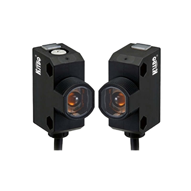
Components of a 4-Wire Photoelectric Sensor
A standard 4-wire photoelectric sensor consists of several key parts: power terminals, output terminals, and a sensing element. The power wires are usually labeled as V+ (positive) and V- (negative) or COM (common), providing the necessary voltage, often 12-24V DC, for the sensor's operation. The output wires include a normally open (NO) and a normally closed (NC) contact, or sometimes a single output with a complementary signal. These outputs switch states when an object is detected, triggering external devices. Additionally, the sensor may have indicator LEDs for power and output status, aiding in troubleshooting. It's essential to refer to the manufacturer's datasheet for specific wire colors and functions, as they can vary by brand. Common wire color codes include brown for V+, blue for V- or COM, black for NO output, and white for NC output.
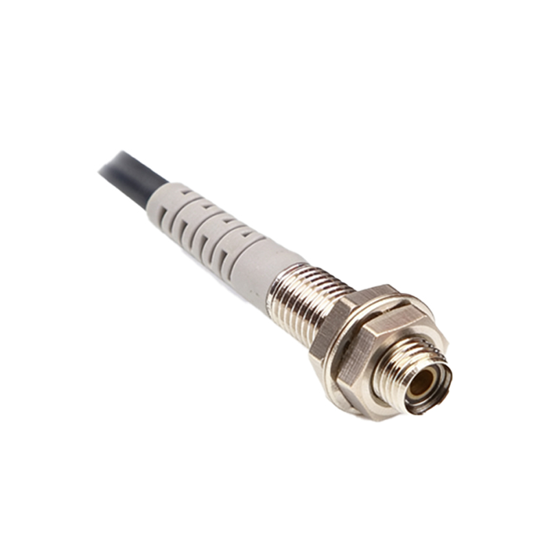
Step-by-Step Wiring Diagram Explanation
To wire a 4-wire photoelectric sensor, start by identifying the power source. Connect the V+ wire (often brown) to the positive terminal of the DC power supply, and the V- or COM wire (usually blue) to the negative terminal. This powers the sensor's internal circuitry. Next, for the output connections, if using a normally open output, link the black wire to the input of a PLC or relay. The white wire, if present for NC, can be connected to an alternative circuit or left unused if not needed. Ensure all connections are secure and insulated to prevent short circuits. A typical diagram shows the sensor interfacing with a load, such as a lamp or motor, through the output wires. For example, when an object is detected, the NO contact closes, completing the circuit and activating the load. Always verify the voltage and current ratings to match the sensor and connected devices.

Common Applications and Setup Tips
Photoelectric sensors with 4-wire setups are employed in diverse industrial scenarios. In conveyor systems, they detect items for sorting or counting. In safety applications, they monitor access points to prevent accidents. To optimize performance, consider the sensing range and environmental factors like dust or light interference. For retro-reflective sensors, align the reflector properly to ensure accurate detection. In through-beam types, position the emitter and receiver opposite each other. Regular maintenance, such as cleaning lenses and checking connections, prolongs sensor life. When troubleshooting, use a multimeter to test voltage and continuity. If the sensor fails to trigger, inspect the wiring diagram for errors, such as reversed polarity or loose terminals. Implementing these tips can reduce downtime and improve operational efficiency in automated processes.
Safety Precautions and Best Practices
When working with photoelectric sensor wiring, safety is paramount. Always disconnect power before making connections to avoid electric shock or equipment damage. Use appropriate tools, such as insulated screwdrivers and wire strippers, and follow local electrical codes. Label wires clearly to prevent confusion during installation or repairs. For complex systems, document the wiring diagram for future reference. Test the sensor with a non-critical load first to ensure correct operation. Additionally, consider using surge protectors or fuses to safeguard against voltage spikes. By adhering to these best practices, you can ensure a reliable and safe installation, minimizing risks in industrial environments. This proactive approach supports long-term functionality and compliance with industry standards.