Introduction to Photoelectric Sensors
Photoelectric sensors are widely used in industrial automation for detecting the presence, absence, or position of objects without physical contact. They operate by emitting a light beam, typically from an LED or laser diode, and then measuring the amount of light received by a photodetector. The basic structure of a photoelectric sensor consists of several key components that work together to ensure accurate and reliable detection. Understanding these components is essential for engineers and technicians involved in system design, installation, and maintenance. This article provides a detailed explanation of the basic structure diagram of a photoelectric sensor, highlighting each part's function and importance in the overall system.
Light Emitting Element
The light emitting element is the core component responsible for generating the light beam used for detection. In most photoelectric sensors, this element is an infrared LED or a visible red LED, although laser diodes are also common in high-precision applications. The choice of light source depends on factors such as detection range, environmental conditions, and required accuracy. The emitting element is housed within a protective casing that includes a lens to focus the light into a narrow beam. This focused beam enhances the sensor's ability to detect small objects or operate over longer distances. The wavelength of the emitted light is carefully selected to match the sensitivity of the photodetector, ensuring optimal performance.
Photodetector and Receiver Circuit
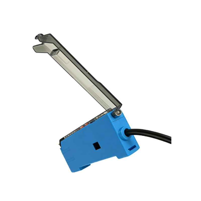
Opposite the light emitting element is the photodetector, which captures the light beam after it interacts with the target object. Common photodetectors include phototransistors, photodiodes, or integrated receiver modules. The photodetector converts the received light into an electrical signal, which is then processed by the receiver circuit. This circuit amplifies the signal and compares it to a predefined threshold to determine the presence or absence of an object. Advanced sensors may include additional features like background suppression or analog output for distance measurement. The receiver circuit is designed to filter out ambient light and electrical noise, ensuring stable operation in various industrial environments.
Optical System and Housing
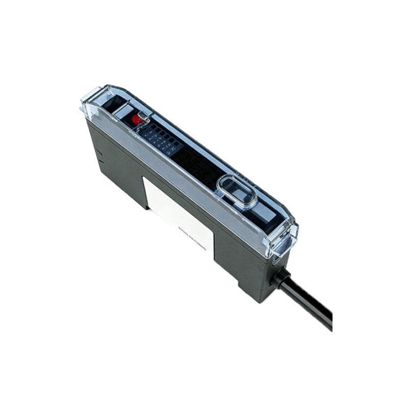
The optical system comprises lenses, filters, and apertures that shape and direct the light beam. The emitter lens collimates the light into a parallel beam, while the receiver lens focuses incoming light onto the photodetector. Some sensors incorporate polarizing filters to reduce reflections from shiny surfaces, or spectral filters to block unwanted wavelengths. The housing, typically made of durable materials like stainless steel or engineered plastics, protects the internal components from dust, moisture, and mechanical impact. It also includes mounting threads or brackets for easy installation. The design of the housing ensures proper alignment between the emitter and receiver, which is critical for consistent performance.
Control and Output Section
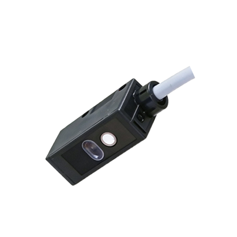
The control section processes signals from the receiver circuit and generates the sensor's output. This includes a microcontroller or dedicated IC that handles logic functions, such as switching between light-on and dark-on modes, adjusting sensitivity, or implementing timers. The output stage provides a digital signal (e.g., NPN/PNP transistor) or analog signal (e.g., 0-10V, 4-20mA) to interface with PLCs, relays, or other control systems. Many sensors feature indicator LEDs for status monitoring and teach-in buttons for quick configuration. The control section may also support communication protocols like IO-Link for advanced diagnostics and parameter setting, enhancing integration into smart factory networks.
Wiring and Connection Interface
Photoelectric sensors are equipped with wiring terminals or connectors for power supply and signal output. Standard configurations include 3-wire DC sensors (positive, negative, and output) or 4-wire versions with dual outputs. The connection interface is designed for easy installation, often featuring screw terminals, M8/M12 connectors, or flying leads with color-coded cables. Proper wiring is crucial to avoid electrical interference and ensure reliable operation. Manufacturers provide detailed datasheets specifying voltage ranges, current consumption, and output types to guide correct integration. Additionally, some sensors offer reverse polarity protection and short-circuit safeguards to prevent damage during installation or maintenance.
Application-Specific Variations
While the basic structure remains consistent, photoelectric sensors are adapted for different sensing modes. Through-beam sensors have separate emitter and receiver units, offering long-range detection. Retro-reflective sensors use a reflector to bounce light back to the receiver, simplifying alignment. Diffuse sensors house both emitter and receiver in one unit, detecting objects based on reflected light. Each variation modifies the optical path or housing design to suit specific applications, such as object counting, edge detection, or color recognition. Engineers must select the appropriate type based on factors like object size, surface properties, and environmental challenges to achieve optimal results.
Conclusion and Best Practices
Understanding the basic structure diagram of a photoelectric sensor is fundamental for effective application in industrial settings. Key components—light emitting element, photodetector, optical system, housing, control section, and wiring interface—work in harmony to provide non-contact detection. Regular maintenance, such as cleaning lenses and checking alignment, ensures long-term reliability. When selecting a sensor, consider parameters like sensing distance, response time, and environmental ratings. By leveraging this knowledge, engineers can design robust automation systems that improve productivity and safety. For further details, refer to manufacturer diagrams and technical manuals tailored to specific sensor models.