Understanding 3-Wire Proximity Sensor Fundamentals
A 3-wire proximity sensor is a fundamental component in modern industrial automation, designed to detect the presence or absence of an object without physical contact. Unlike 2-wire sensors that are wired in series with the load, 3-wire sensors provide a dedicated path for power supply and a separate switching output, offering superior performance and reliability. The three wires are universally color-coded or labeled: brown for the positive supply voltage (V+), blue for the common negative or 0V (V-), and black for the switched output signal. This configuration allows for two primary output types: NPN (sinking) and PNP (sourcing). Understanding this basic architecture is crucial before proceeding with any wiring installation, as incorrect connections can lead to sensor failure or damage to the control system.
Power Supply Requirements and Precautions
The correct power supply is the cornerstone of reliable sensor operation. Most industrial 3-wire DC proximity sensors operate within a range of 10-30V DC. It is imperative to verify the sensor's datasheet for the exact voltage specifications. A stable, regulated DC power source must be used. Fluctuations or spikes in voltage can cause erratic behavior or permanent damage. Always ensure the power is disconnected before making or altering any connections. Furthermore, implement proper fusing on the supply line to protect the sensor from overcurrent conditions. The brown wire connects to the positive terminal of the DC power supply, and the blue wire connects to the negative terminal. Consistency in grounding is vital; the blue wire should ultimately connect to the same common ground point as the PLC or controller to avoid ground loop issues.
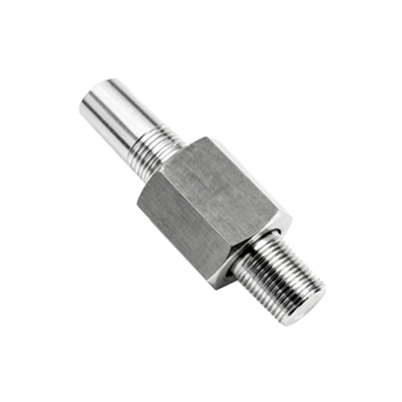
Wiring a PNP (Sourcing) Output Sensor
A PNP-type 3-wire sensor is characterized by its sourcing output. In this configuration, when the sensor detects a target, it switches the output to source current from the positive supply. To wire a PNP sensor, connect the brown wire to the positive DC supply terminal (e.g., +24V). Connect the blue wire to the negative DC supply terminal (0V or common). The black output wire is connected to the input channel of your programmable logic controller (PLC), relay, or other load device. The other side of that load must then be connected back to the common negative (0V) of the power supply. Essentially, the sensor acts as a switch between the load and positive voltage. PNP sensors are often the standard in many regions and are typically used with PLCs that have sinking-type input modules.
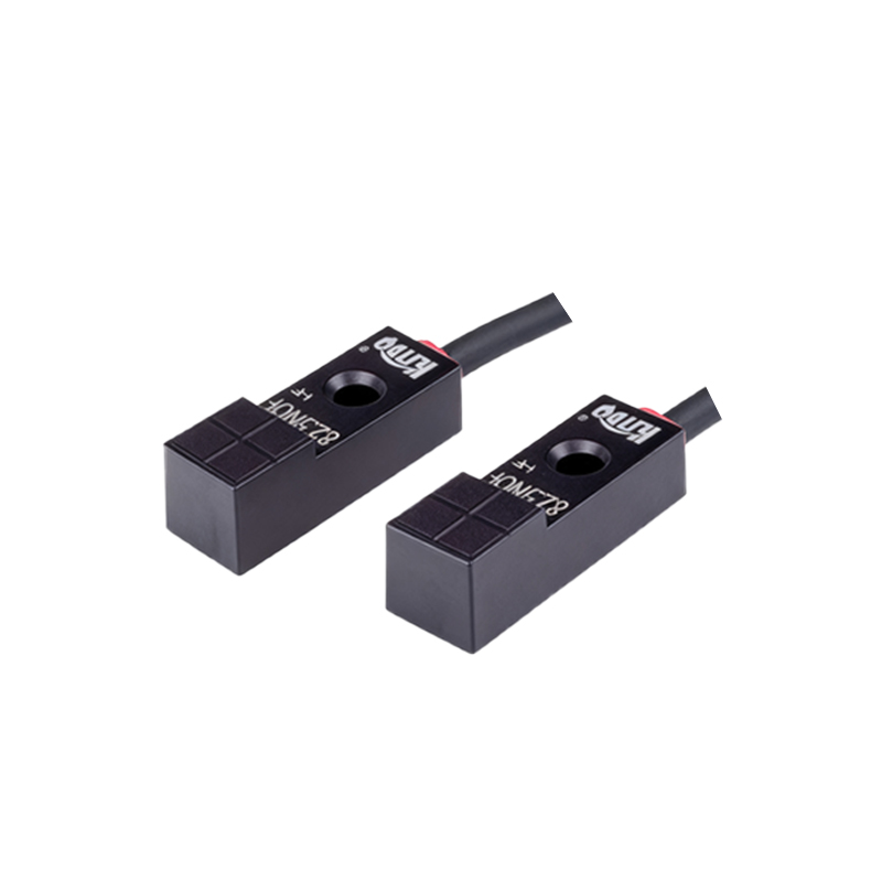
Wiring an NPN (Sinking) Output Sensor
An NPN-type 3-wire sensor operates with a sinking output. When activated, it switches the output to sink current to the negative common. The power connections remain identical: brown to positive (+V), blue to negative (0V). The key difference lies in the output connection. The black output wire is connected to the load (e.g., the PLC input). However, the other side of that load must be connected to the positive supply voltage. In this setup, the sensor acts as a switch between the load and ground. NPN wiring is common in certain geographic markets and is used with PLCs that have sourcing-type input modules. It is critical never to confuse NPN and PNP wiring diagrams, as this will prevent the system from functioning and may cause damage.
Connecting to a PLC Digital Input Module
Integrating the sensor with a PLC is a frequent application. First, identify whether your PLC's digital input module is configured for sinking (accepts current from a PNP sensor) or sourcing (provides current to an NPN sensor). For a sinking input card, use a PNP sensor. Wire the sensor's black wire to the specific input terminal (e.g., I0.0). The common terminal of the input card is connected to 0V. For a sourcing input card, use an NPN sensor. Wire the sensor's black wire to the input terminal, and ensure the common terminal of the input card is connected to +24V. Always refer to the PLC hardware manual for definitive terminal designations and electrical specifications. Proper shielding of the cable, especially in environments with electromagnetic interference, is highly recommended.
Implementing Load Devices and Protective Circuits
The output of the proximity sensor often drives a load such as a relay coil, indicator lamp, or PLC input. It is essential to ensure the load's current draw does not exceed the sensor's maximum switching capacity, typically stated in milliamps (mA) on its datasheet. For inductive loads like relay coils, always use a protective fly