Introduction to Through-Beam Photoelectric Sensors
Through-beam photoelectric sensors, also known as opposed-mode sensors, consist of two separate units: a transmitter and a receiver. The transmitter emits a continuous beam of light, typically infrared or visible red, which is detected by the receiver. An object is sensed when it interrupts this light beam. This configuration offers the longest sensing range and highest reliability among photoelectric sensing modes, making it ideal for applications requiring precise detection over distances or in challenging environments with dust, dirt, or vibration. Understanding the correct wiring procedure is fundamental to ensuring optimal performance and system safety.
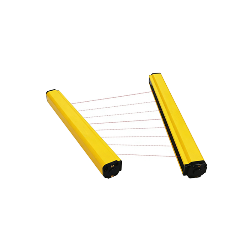
Components and Wiring Terminology
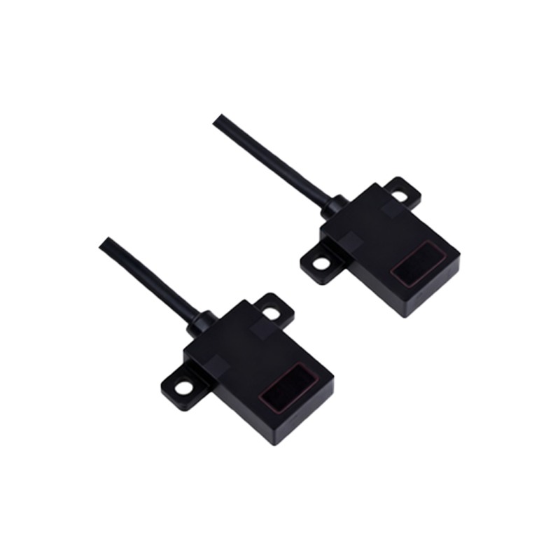
Before beginning the wiring process, familiarize yourself with the key components. The sensor units will have a connection head or integral cable with several wires. Standard wire color coding, though not universally mandatory, often follows this convention: Brown wire for the positive DC supply voltage (typically +12V to +24V DC), Blue wire for the common or 0V DC supply, Black wire for the output signal (normally open or normally closed), and sometimes a White wire for a complementary output or function wire. Always consult the specific datasheet or manual for your sensor model, as colors and functions can vary by manufacturer. The output type is crucial; it is usually an NPN (sinking) or PNP (sourcing) transistor output.
Power Supply Connection
The first step is to provide a stable DC power source. Connect the Brown wire from both the transmitter and the receiver to the positive terminal of your DC power supply. Connect the Blue wire from both units to the negative or 0V terminal of the same power supply. It is critical that both units share the same power source ground to ensure a common reference point. Use a power supply that matches the sensor's voltage rating, commonly 12-24V DC. Ensure polarity is correct; reversing power wires can permanently damage the sensor. For added protection, consider installing a fuse in the positive line close to the power source.
Output Signal Wiring
The receiver unit handles the output signal. Its Black wire (or designated output wire) is connected to your control device, such as a programmable logic controller (PLC) input, relay, or indicator. The wiring differs for NPN and PNP outputs. For a PNP (sourcing) output, the Black wire provides positive voltage when the light beam is uninterrupted (or interrupted, depending on logic). Connect this Black wire to the PLC input point. The PLC input's common terminal is then connected to the power supply's 0V (Blue wire). For an NPN (sinking) output, the Black wire acts as a path to 0V when active. Connect the PLC input point to the positive supply, and connect the sensor's Black wire to the PLC input's common terminal, which is then linked to 0V. Always verify the load (PLC input) compatibility.
Connecting to a PLC Input Module
A typical connection to a sinking (NPN-compatible) PLC input module involves the following steps. First, provide 24V DC to the sensor's Brown wire and 0V to its Blue wire. For the receiver's output, connect the Black wire (NPN output) directly to the specific PLC input channel terminal (e.g., I0.0). Next, internally within the PLC cabinet, connect the common terminal of that input module group to the 24V DC positive rail. This creates a circuit: 24V+ -> PLC input common -> input channel -> sensor Black wire -> sensor internal transistor -> 0V. When the beam is broken, the NPN transistor switches on, completing the circuit to 0V and allowing current to flow, which the PLC registers as an active input.
Alignment and Testing Procedures
After wiring, power on the system. Most sensors have a built-in alignment aid, such as a red LED on the receiver that illuminates when it receives sufficient light from the transmitter. Precisely align the transmitter and receiver so that the beam is centered. The receiver's indicator should be steadily lit. Now, interrupt the beam with the target object. The receiver's output indicator (often a yellow or green LED) should change state, and the connected PLC input or relay should activate. Use this test to verify both wiring correctness and proper sensor function. Ensure the beam is not obstructed by ambient light or reflective surfaces, which can cause false triggers.
Safety and Installation Best Practices
Always disconnect power before wiring. Use conduit or cable carriers in industrial environments to protect wires from physical damage, oils, and chemicals. Secure cables with strain relief to prevent tension on the electrical connections. Maintain the sensor's specified environmental ratings for temperature, humidity, and ingress protection (IP rating). For long-distance applications, use shielded cables and ground the shield at one end to the control panel to minimize electrical noise interference. Periodically clean the lenses of both transmitter and receiver to prevent false operations due to dirt accumulation. Finally, document your wiring diagram for future maintenance and troubleshooting reference.