Introduction to 5-Wire Proximity Sensors
In the realm of industrial automation and control systems, proximity sensors are indispensable components for non-contact object detection. Among the various configurations available, the 5-wire proximity sensor stands out for its unique operational characteristics and wiring scheme. Unlike their 2-wire or 3-wire counterparts, 5-wire sensors incorporate a dedicated pair of wires for power supply and a separate pair for the switching output, with the fifth wire serving as a common reference or ground. This design fundamentally separates the power and signal circuits, offering enhanced performance and reliability in demanding electrical environments. Engineers often select this type for applications requiring high precision, stability, and protection against electrical noise.
Internal Circuitry and Operating Principle
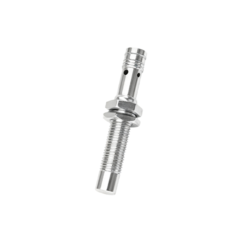
The core of a 5-wire proximity sensor typically involves an oscillator circuit, a detection coil, and a solid-state output stage. The oscillator generates a high-frequency electromagnetic field from the sensor's active face. When a metallic target enters this field, eddy currents are induced, causing a change in the oscillation amplitude. This change is detected and processed by the internal circuitry. The key distinction lies in its output configuration: it utilizes two separate transistors for switching, often in a complementary (push-pull) arrangement. One transistor connects the output to the positive supply (sourcing), and the other connects it to the common/negative (sinking). This allows for a versatile output that can handle different load connections.
Detailed Wiring Configuration and Color Codes
Correct wiring is paramount for safe and functional operation. While color codes can vary by manufacturer, a common standard (following IEC/EN 60947-5-2) is widely adopted. The typical wiring for a 5-wire DC sensor is as follows: Brown wire connects to the positive DC supply voltage (e.g., +24V DC). Blue wire connects to the negative DC supply voltage (0V DC) or ground. This pair forms the dedicated power circuit for the sensor's internal electronics. The output circuit consists of a Black wire (normally the switching output), a White wire (often a complementary output or second output), and a Gray wire (common terminal for the outputs). It is crucial to consult the specific sensor's datasheet, as white and black wires can sometimes be configured for normally-open (NO) or normally-closed (NC) operation.
Output Types: Sourcing (PNP) and Sinking (NPN) Modes
A defining feature of the 5-wire sensor is its inherent ability to support both PNP (sourcing) and NPN (sinking) output configurations without physical modification. This is achieved through its two-output transistor design. In a typical setup, the black wire acts as the main output. To configure it as a PNP (sourcing) output, the load is connected between the black wire and the negative supply (blue). The gray wire is connected to the positive supply. In this mode, the sensor "sources" current to the load when active. Conversely, for an NPN (sinking) configuration, the load is connected between the positive supply and the black wire, with the gray wire connected to the negative supply. Here, the sensor "sinks" current from the load to ground when activated.
Key Advantages and Application Scenarios
The separation of power and output circuits in 5-wire sensors provides significant benefits. It offers superior noise immunity, as electrical disturbances on the load side are less likely to affect the sensor's internal logic. This makes them ideal for environments with heavy machinery, variable frequency drives, or welding equipment. The dual-transistor output allows for direct interface with both sourcing and sinking input modules on Programmable Logic Controllers (PLCs), providing exceptional flexibility in system design. Common applications include precise positioning in machine tools, robotic end-effector sensing, material handling systems, and safety interlocking where reliable signal integrity is non-negotiable.
Installation Considerations and Troubleshooting Tips
Proper installation ensures optimal performance and longevity. Maintain the recommended sensing distance and consider the target material's shape, size, and composition (e.g., steel, aluminum). Ensure the sensor body is correctly mounted and grounded if specified. For troubleshooting, a systematic approach is best. First, verify the power supply voltage across the brown and blue wires. Next, check the output state with a multimeter or a PLC input indicator. If the sensor does not switch, confirm the wiring configuration (PNP vs. NPN) matches the load. Also, inspect for metallic debris on the sensing face and ensure the target is within the specified switching range. Understanding the voltage potential between the output wires (black/g