Introduction to Photoelectric Sensor Interface Terminology
In the realm of industrial automation and control systems, photoelectric sensors are indispensable components for detecting the presence, absence, or position of objects. Effective integration of these sensors into a larger control architecture hinges on a clear understanding of their interface specifications. These specifications are frequently denoted by standardized English abbreviations, which can be a source of confusion for both novice and experienced engineers. This guide aims to demystify these common interface abbreviations, providing clarity on their functions, electrical characteristics, and typical applications. Mastering this terminology is crucial for selecting the correct sensor, ensuring reliable communication with Programmable Logic Controllers (PLCs), and designing robust electrical circuits.
Key Interface Types and Their Abbreviations
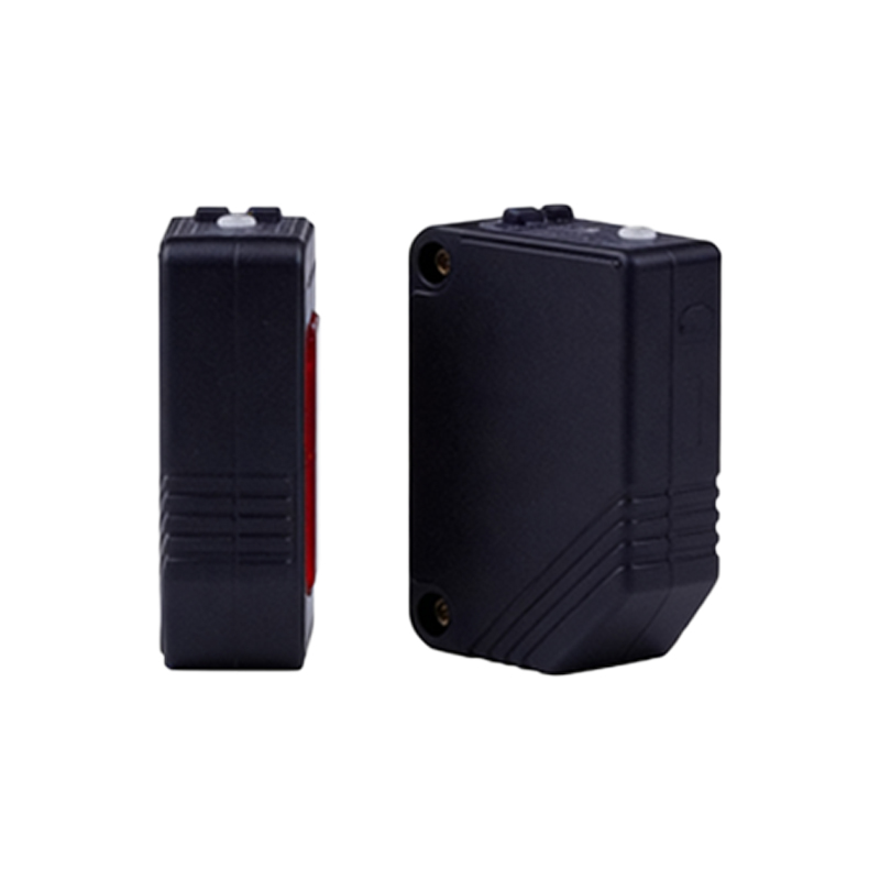
Photoelectric sensor outputs are primarily categorized by their switching technology and electrical configuration. The most fundamental distinction is between Digital (Discrete) and Analog interfaces. For digital outputs, common abbreviations include PNP and NPN. A PNP (Positive-Negative-Positive) output, also known as a sourcing output, switches the positive voltage supply to the load. Conversely, an NPN (Negative-Positive-Negative) output, or sinking output, switches the ground connection to the load. The choice between PNP and NNP is often dictated by regional conventions and the input type of the receiving controller, with PNP being prevalent in Europe and NPN in some Asian markets. Another critical digital output type is the Push-Pull (or Totem Pole) output, which combines the benefits of both PNP and NPN, allowing connection to either sinking or sourcing inputs without concern for polarity.
Analog and Specialized Output Interfaces
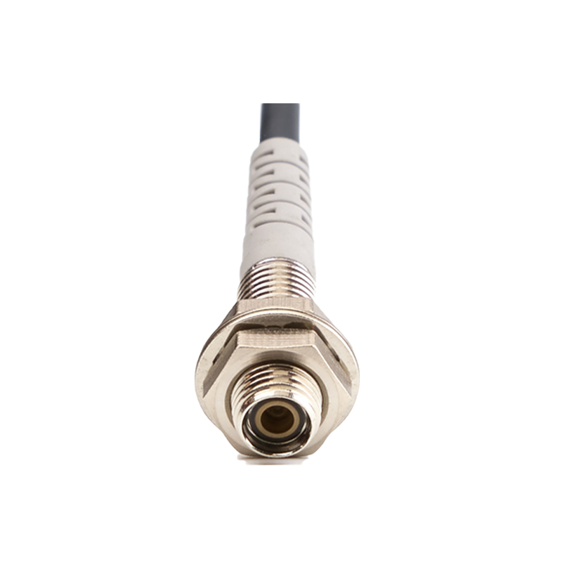
Beyond simple on/off signals, many applications require proportional feedback. This is where analog output interfaces come into play. Common abbreviations are 0-10V and 4-20mA. A 0-10V output provides a voltage signal linearly proportional to the measured parameter, such as distance or light intensity. The 4-20mA current loop output is highly favored in industrial environments for its superior noise immunity over long distances; the 4mA "live zero" allows the system to distinguish between a valid low signal and a broken wire. For communication-intensive applications, IO-Link has emerged as a pivotal standard. IO-Link is a point-to-point serial communication protocol (IEC 61131-9) that enables bidirectional data exchange beyond simple switching. It allows for parameter configuration, advanced diagnostics, and process value transmission from a single sensor, revolutionizing device integration and maintenance.

Input Power Supply and Protection Circuitry
The interface discussion is incomplete without considering the sensor's input requirements, typically abbreviated as VDC. This denotes the required Direct Current operating voltage range, such as 10-30 VDC, which is standard for most industrial sensors. Protection features are equally important and are indicated by specific abbreviations. Reverse Polarity Protection (RPP) safeguards the sensor from damage if the power supply leads are connected incorrectly. Short-Circuit Protection (SCP) is a critical feature that allows the output to withstand an accidental short to ground or supply voltage without permanent damage. Additionally, Surge Protection is often implemented to guard against voltage spikes on the supply or output lines, ensuring longevity in electrically noisy environments.
Selecting the Right Interface for Your Application
Choosing the appropriate interface abbreviation on a sensor datasheet requires careful consideration of the system architecture. First, identify the input type of your controller (PLC, relay, etc.). A sourcing input (common on many PLCs) requires an NPN sensor output, while a sinking input requires a PNP sensor. For analog sensing, decide between voltage (0-10V) for simpler, shorter-distance wiring or current (4-20mA) for longer runs in electrically harsh areas. When future-proofing a system or requiring detailed device data, specifying an IO-Link interface is highly advantageous. Always verify that the sensor's output configuration (e.g., Normally Open (NO) or Normally Closed (NC)) matches the required control logic. Consulting the manufacturer's wiring diagrams, which universally use these standard abbreviations, is an essential final step before installation.
Conclusion and Best Practices
Understanding abbreviations like PNP, NPN, IO-Link, 4-20mA, and VDC is fundamental to the successful deployment of photoelectric sensors. These terms form a concise language that describes critical electrical and functional properties. When designing or troubleshooting a system, always cross-reference the sensor's interface markings with the controller's specifications. Prioritize sensors with robust protection features like SCP and RPP to enhance system reliability. As industrial networks become more intelligent, familiarity with communication-enabled interfaces like IO-Link will become increasingly important. By internalizing this lexicon of interface abbreviations, engineers can ensure optimal sensor selection, seamless integration, and ultimately, a more efficient and reliable automated system.