Introduction to Photoelectric Sensor Wiring
Photoelectric sensors are indispensable components in modern industrial automation, providing non-contact detection of objects through light beams. Among various configurations, the 4-wire photoelectric sensor is widely adopted for its balanced functionality, combining both normally open (NO) and normally closed (NC) output signals along with separate power supply lines. This wiring setup enhances flexibility in control systems, allowing for diverse logic implementations in machinery safety, production line monitoring, and material handling. Understanding the correct 4-wire connection method is crucial for ensuring reliable operation, preventing electrical faults, and maximizing sensor lifespan in harsh industrial environments.
Identification of 4-Wire Sensor Terminals
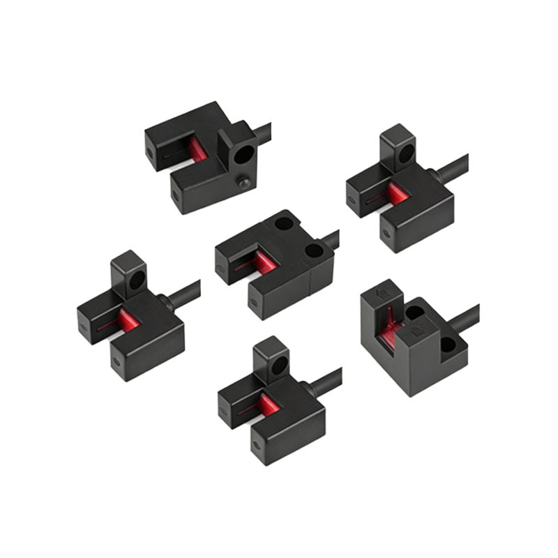
A standard 4-wire photoelectric sensor typically includes clearly labeled terminals or color-coded wires. Common designations are: brown wire for positive DC supply (V+), blue wire for negative DC supply (0V or common), black wire for normally open output (NO), and white wire for normally closed output (NC). Some models may use alternative colors like red for V+ and black for common, so always refer to the manufacturer's datasheet. The sensor housing often indicates terminal functions with symbols: V+ for power positive, V- for power negative, NO for normally open output, and NC for normally closed output. Proper identification prevents reverse polarity connections that could damage internal circuitry.
Power Supply Connection Procedure
Connect the brown wire (or red wire) to the positive terminal of a DC power source, typically 10-30 VDC, ensuring voltage matches sensor specifications. The blue wire (or black wire) attaches to the negative terminal or ground. Use shielded cables in electrically noisy environments to minimize interference. Implement a separate fused power line for sensors in critical applications to isolate faults. Verify polarity with a multimeter before energizing to avoid short circuits. Stable power is essential; voltage fluctuations beyond ±10% may cause erratic behavior. For multiple sensors, consider a regulated power supply with adequate current capacity, as each sensor draws 10-50 mA depending on model and load.
Output Wiring to Control Devices
The black wire (NO output) connects to the input module of a PLC, relay, or controller. When the sensor detects an object, this circuit closes, sending a signal. The white wire (NC output) provides the opposite logic: circuit opens upon detection. Choose based on system requirements—NO for active-high signals, NC for fail-safe applications. Ensure load current does not exceed sensor ratings, usually 100-200 mA. For inductive loads like relays, add a flyback diode to suppress voltage spikes. Use twisted-pair cables for output lines to reduce electromagnetic interference. Test outputs with a dummy load before integrating into the control system to confirm switching functionality.
Wiring Diagrams and Practical Examples
A typical diagram shows DC power connected to V+ and V- terminals. The NO output wire links to a PLC digital input, while the NC output wire may connect to an alarm circuit. In conveyor systems, NO wiring can trigger a stop when an object is detected, whereas NC wiring might activate if the beam is broken unexpectedly. For bidirectional monitoring, use both outputs: NO for presence detection and NC for absence verification. Always follow regional electrical codes—use conduit or cable trays for protection, and maintain proper wire gauge (e.g., 18-22 AWG for low-current signals). Label all wires at both ends to simplify troubleshooting.
Common Mistakes and Troubleshooting Tips
Frequent errors include swapping NO and NC wires, causing inverted logic; mixing power and output terminals, leading to sensor failure; or using unshielded cables in high-noise areas, resulting in false triggers. If the sensor fails to operate, check power voltage, polarity, and fuse condition. Measure output signals with a multimeter: NO should show 0 V when inactive and near supply voltage when active. Inspect for loose connections, cable damage, or environmental factors like dirt obstructing the lens. Reset the sensor by cycling power, and consult the manual for diagnostic LED indicators—steady green often means normal operation, while flashing red may indicate alignment issues.
Safety and Maintenance Considerations
Disconnect power before wiring to prevent electric shock or equipment damage. Use lockout/tagout procedures in industrial settings. Ensure sensors are rated for the operating environment—IP67 for dust and water resistance in washdown areas. Regularly clean lenses with a soft cloth to maintain sensitivity. Calibrate sensing distance periodically, especially for diffuse-reflective models. Keep wiring away from high-voltage lines to avoid induction noise. Document all connections in system schematics for future reference. For complex installations, consider professional training on photoelectric sensor integration to uphold safety standards and optimize performance.
Conclusion and Best Practices
Mastering the 4-wire photoelectric sensor connection method enhances system reliability and adaptability. Always prioritize manufacturer guidelines, use quality components, and perform thorough testing. This approach minimizes downtime, supports efficient automation, and ensures long-term operational integrity in diverse industrial applications. As technology evolves, staying updated with wiring standards and sensor advancements will continue to be key for engineers and technicians in the field.