Introduction to Inductive Hall Effect Proximity Technology
In the realm of industrial automation and control, the reliable detection of metallic objects without physical contact is paramount. Inductive proximity sensors have long served this purpose, but the integration of Hall Effect technology creates a specialized and highly effective variant: the inductive Hall Effect proximity switch. This device merges the fundamental operating principle of standard inductive sensors with the precise, magnetic field-sensing capability of a Hall Effect element. The core function remains the detection of ferrous (iron and steel) targets, but the internal sensing mechanism and output characteristics are distinctly different, offering unique advantages in specific applications. Essentially, it is a proximity switch specifically optimized for sensing ferromagnetic materials by detecting changes in a magnetic field, rather than the eddy current damping used in conventional inductive sensors.
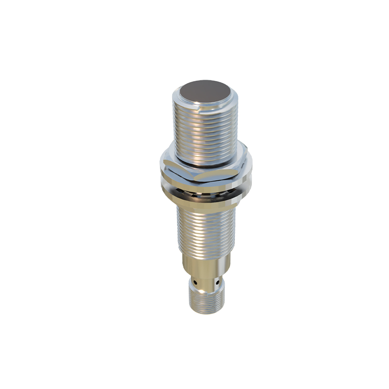
Core Working Principle and Internal Mechanism
The operation of an iron-sensing Hall Effect proximity switch hinges on a simple yet elegant physical phenomenon. Inside the sensor, a permanent magnet generates a static magnetic field. A Hall Effect IC (integrated circuit) is positioned within this field. When no target is present, the Hall IC experiences a baseline magnetic flux density and outputs a specific signal state, typically a low voltage or an "off" signal for a normally-open configuration. As a ferromagnetic object, such as an iron gear tooth or a steel piston, approaches the active face of the sensor, it enters the magnetic field. The ferrous material has high magnetic permeability, meaning it "conducts" magnetic flux easily. This causes the magnetic field lines from the permanent magnet to become concentrated or distorted through the target. This change in the magnetic field's strength and/or direction is precisely measured by the Hall Effect IC. Once the flux density crosses a predefined threshold, the IC triggers the sensor's solid-state switching circuitry, changing its output state.
Key Advantages Over Standard Inductive Sensors
This technology offers several compelling benefits. First, it provides exceptional switching accuracy and repeatability. The Hall Effect element responds to the exact point where magnetic flux reaches a specific level, resulting in very precise and consistent switch points, even at high speeds. Second, these sensors typically have a longer operating distance for a given size compared to some standard inductive types when detecting ferrous metals. Third, the switching frequency or response speed can be extremely high, often in the kilohertz range, making them ideal for counting fast-moving gear teeth or monitoring rapid rotational speeds. Fourth, they are largely immune to environmental factors like non-conductive dust, oil, or coolant films that might coat the sensing face, as these materials do not affect the magnetic field. Finally, the output signal from the Hall IC is inherently clean and digital, simplifying interface with modern programmable logic controllers (PLCs).
Typical Industrial Applications and Use Cases
Iron-sensing Hall Effect proximity switches find their niche in applications demanding precision, speed, and reliability with ferrous targets. A primary application is rotational speed sensing. They are extensively used as gear tooth sensors in automotive transmissions, industrial gearboxes, and engine timing systems to monitor RPM and angular position. In factory automation, they serve as end-of-travel or position verification sensors for hydraulic and pneumatic cylinders with magnetic pistons. They are crucial in conveyor systems for detecting metal parts, in metalworking for tool position detection, and in safety systems for verifying the closed position of heavy iron doors or guards. Their ability to function in dirty environments also makes them suitable for agricultural and construction machinery.
Critical Selection Parameters and Installation Guidelines
Selecting the correct sensor requires careful consideration of several parameters. The sensing distance, or operating point, must be specified based on the target material (pure iron is the reference), target size, and required installation clearance. The electrical output type is vital: common options include NPN (sinking) or PNP (sourcing) transistor outputs, and some offer analog or push-pull outputs. The supply voltage range (e.g., 5-30V DC) must match the control system. Environmental ratings, particularly the Ingress Protection (IP) rating for dust and water resistance, and temperature range are essential for durability. For installation, maintaining the correct orientation relative to the target and ensuring the recommended lateral and axial gaps between the sensor and the target (if applicable) are critical for reliable operation. Shielding from strong external magnetic fields is also an important consideration.
Common Challenges and Troubleshooting Tips
While robust, these sensors can encounter issues. A frequent problem is incorrect installation distance; if the target is beyond the specified sensing range, no switching will occur. Conversely, if installed too close, it may fail to release when the target moves away. Electrical issues like incorrect wiring, voltage spikes