Understanding False Triggers in Photoelectric Sensing
Photoelectric sensors are renowned for their reliability in industrial automation, yet false readings remain a persistent challenge. A false trigger occurs when the sensor's output changes state without a legitimate target object being present in its detection zone. Conversely, a missed detection happens when a valid target passes through without being registered. These inaccuracies can lead to production line stoppages, quality control failures, and costly downtime. The root causes are rarely a simple sensor failure; instead, they often stem from environmental interference, improper installation, or a mismatch between the sensor's specifications and the application's requirements. Diagnosing the issue requires a systematic approach, examining the entire sensing system from the light emitter to the receiver and the processing circuitry.
Environmental Interference: The Primary Culprit
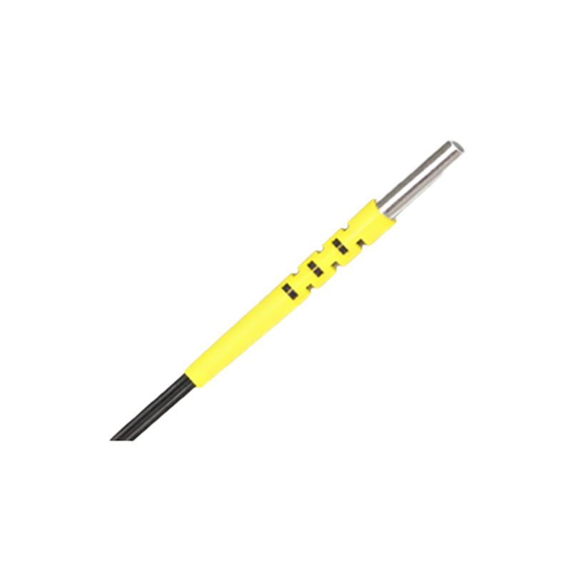
The operating environment is the most common source of photoelectric sensor inaccuracy. Ambient light, particularly direct sunlight or strobe lighting from welding equipment, can flood the receiver with photons, causing it to saturate and trigger falsely. Dust, steam, oil mist, or condensation on the lens can scatter or attenuate the emitted light beam, reducing signal strength and leading to missed detections. Vibrations can cause momentary misalignment in through-beam sensors, breaking the beam path. Temperature extremes can also affect the performance of the sensor's internal electronics and the wavelength of the light source, albeit minimally for modern, robust models. Shielding the sensor from ambient light with a tube or hood and ensuring a clean, stable mounting are the first defensive steps.
The Critical Role of Sensor Selection and Setup
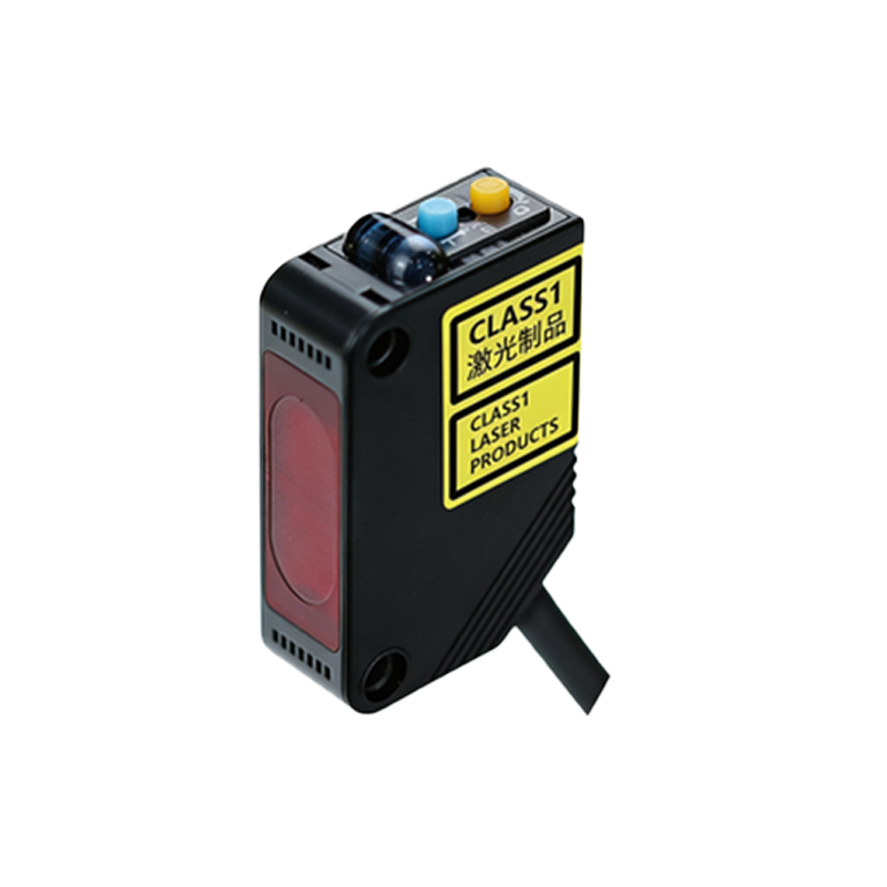
Choosing the wrong sensor type for the application is a fundamental error. A diffuse reflective sensor might be selected for its simplicity, but if the target has a low-reflectivity, dark, or glossy surface, it can cause unreliable operation. For such targets, a retro-reflective sensor with a polarizing filter or a through-beam sensor is more appropriate. Incorrect setup is equally problematic. The sensitivity potentiometer, or "teach" function, is often misadjusted. Setting it too high can make the sensor susceptible to background reflections or dust; setting it too low can cause it to miss smaller or less reflective objects. The sensing range must also be respected—operating a sensor too close to its maximum range leaves no margin for signal degradation.
Electrical Noise and Supply Issues
Electrical noise from nearby motors, variable frequency drives (VFDs), or high-voltage cables can induce spurious signals in the sensor's output circuit, mimicking a valid trigger. This is especially prevalent in sensors with analog outputs or long, unshielded cable runs. Power supply problems, such as voltage spikes, sags, or ripple, can reset the sensor's internal logic or cause unstable operation. Ensuring proper grounding, using shielded cables with the drain wire grounded at the controller end, and installing ferrite cores or line filters can significantly mitigate electrical noise. A stable, regulated power supply dedicated to the control system is always recommended.
Mechanical and Optical Alignment Problems
For through-beam and retro-reflective sensors, precise optical alignment is paramount. Even a slight misalignment, which can develop over time due to vibration or thermal expansion, drastically reduces the received light intensity, pushing the signal-to-noise ratio into an unreliable zone. Mechanical issues like a loose mounting bracket or a bent sensor housing will have the same effect. Regular maintenance checks should include verifying alignment with an alignment tool or by observing the sensor's signal strength indicator. For diffuse sensors, the angle of incidence to the target is critical; an oblique angle can reflect the beam away from the receiver.
Target-Related Inconsistencies
The sensor is only half of the equation; the target object itself can be the source of inconsistency. Variations in color, surface finish, material, or even the presence of labels can change its reflectivity. A transparent object, like a glass bottle, may pass undetected by a standard diffuse sensor. The object's size relative to the beam spot also matters—if the beam is larger than a small target, the sensor averages the reflection from the target and the background, potentially causing a weak or fluctuating signal. Using a sensor with a focused beam or a background suppression (BGS) function can solve many target-related issues.
Systematic Troubleshooting and Corrective Actions
A logical troubleshooting sequence is essential. First, observe the application to identify patterns in the failures. Use the sensor's built-in stability or signal strength LED as a diagnostic tool. Temporarily replace the suspect sensor with a known-good unit to isolate the problem. Check all physical connections and cabling for integrity. Verify the power supply voltage at the sensor terminals under load. Adjust the sensitivity setting while monitoring performance, finding the optimal midpoint. If environmental factors are suspected, try temporary shielding or cleaning. For persistent electrical noise, consider relocating cables or adding filtering. Ultimately, the solution may involve selecting a different sensor technology, such as switching from diffuse to through-beam, or employing a sensor with a modulated LED and synchronous detection that is immune to ambient light.
Implementing Preventive Maintenance Practices
Preventing false readings is more efficient than troubleshooting them. Establish a routine maintenance schedule that includes cleaning sensor lenses with appropriate materials, checking and tightening all mechanical mounts, verifying alignment, and inspecting for environmental changes like new light sources or dust-generating equipment. Keep a log of sensor performance and any adjustments made. Training maintenance personnel on the different sensor operating principles (through-beam, retro-reflective, diffuse) and their specific vulnerabilities empowers them to make better initial selections and quicker diagnoses, ensuring long-term system reliability and minimizing disruptive false triggers.