Introduction to Proximity Switch Sensor Technology
Proximity switch sensors, fundamental components in modern industrial automation, operate on the principle of non-contact object detection. These devices emit an electromagnetic field or a beam of electromagnetic radiation and detect changes in the field or return signal. The primary types include inductive, capacitive, ultrasonic, and photoelectric sensors. Inductive sensors detect metallic objects, capacitive sensors respond to both metallic and non-metallic materials, while photoelectric and ultrasonic types offer longer detection ranges. The core advantage lies in their ability to function without physical contact, thereby eliminating mechanical wear and enabling high-speed, reliable operation in harsh environments. Understanding these foundational principles is the first critical step for any engineering team embarking on an independent research and development (R&D) journey.
Strategic Imperatives for In-House R&D
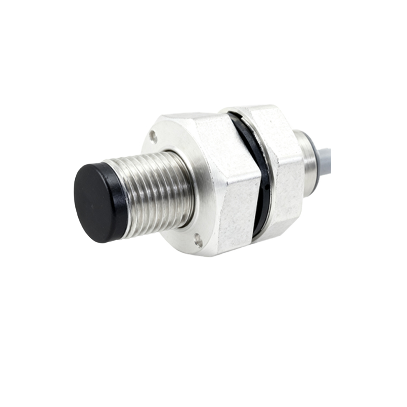
The decision to pursue independent R&D for proximity sensors is driven by several strategic factors. Firstly, it grants complete intellectual property (IP) ownership, protecting proprietary algorithms and designs from competitors. Secondly, it allows for deep customization to meet specific application requirements that off-the-shelf sensors cannot address, such as unique form factors, extreme temperature tolerances, or specialized output signals. Thirdly, it reduces long-term dependency on specific suppliers, mitigating supply chain risks and potentially lowering costs at scale. Finally, in-house development fosters a deeper understanding of the technology within the engineering team, accelerating troubleshooting and future innovation cycles. This strategic control is invaluable in industries like automotive manufacturing, packaging, and material handling where sensor performance is critical.
Core Technical Challenges in Sensor Development
Developing a reliable proximity sensor presents multifaceted engineering challenges. For inductive sensors, designing the oscillator coil and its associated circuitry to achieve a stable, sensitive electromagnetic field is paramount. Engineers must carefully select ferrite cores and winding techniques to optimize the detection range and immunity to electrical noise. For capacitive types, managing stray capacitance and environmental factors like humidity is a constant battle. The sensing electrode design and shield-drive techniques are crucial for stability. Across all types, signal conditioning—amplifying the weak detection signal, filtering out noise, and providing a clean, stable output—requires sophisticated analog and digital circuit design. Furthermore, ensuring electromagnetic compatibility (EMC) to prevent interference with other equipment and meet international standards (e.g., IEC, UL) is a non-trivial task that demands extensive testing.
The Integrated Development Process: From Concept to Prototype
A structured development process is essential for success. It typically begins with a detailed requirements specification, outlining parameters like sensing distance, target material, output type (PNP/NPN, analog, IO-Link), housing material (e.g., stainless steel, PBT), and environmental ratings (IP67, IP69K). The next phase involves schematic design and simulation using tools like SPICE for analog circuits and finite element analysis (FEA) software for modeling electromagnetic or capacitive fields. Printed Circuit Board (PCB) layout is critical, especially for high-frequency oscillator circuits, requiring careful attention to grounding, component placement, and trace routing to minimize noise. Following PCB fabrication, the assembly and programming phase begins, where firmware for smart sensor features (e.g., teach-in, diagnostics) is developed. Rigorous bench testing against the specification then validates the prototype's performance.
Material Science and Component Selection
The performance and durability of a proximity sensor are heavily influenced by material choices. The sensor face, or active surface, is often made from a specialized polymer (like PPS or PBT) for inductive sensors to allow the magnetic field to pass, while capacitive sensors may use a different dielectric material. The housing must provide mechanical strength, chemical resistance, and often electromagnetic shielding. Stainless steel (e.g., 303, 316L) is common for demanding environments. Internally, the quality of electronic components—such as the stability of oscillators, the precision of analog-to-digital converters (ADCs), and the robustness of output transistors—directly impacts reliability and longevity. Sourcing high-grade, temperature-stable components from reputable suppliers is a key factor in achieving a consistent product lifecycle.
Calibration, Testing, and Quality Assurance
No sensor design is complete without a comprehensive calibration and testing regimen. Calibration involves setting the precise switching points and, for analog sensors, ensuring linearity across the measurement range. This often requires automated test fixtures with precision positioning systems. Testing must cover functional parameters (operating distance, hysteresis, repeatability), environmental stress (temperature cycling, vibration, shock), and compliance with EMC and safety standards. Long-term reliability tests, such as continuous operation over thousands of hours, help identify potential failure modes. Implementing a rigorous Quality Assurance (QA) process, potentially following automotive standards