Understanding the Core Principle
Capacitive proximity sensors operate on the fundamental principle of capacitance change. At their heart is an oscillator circuit that generates an electrostatic field emanating from the sensing face or a surrounding guard ring. When a target object enters this active field, it alters the dielectric properties of the space between the sensor and the object. This change modifies the capacitance of the oscillator circuit. The sensor's internal circuitry continuously monitors this capacitance. Once the change reaches a preset threshold, it triggers a solid-state output switch, signaling the object's presence. Unlike inductive sensors that detect only metals, capacitive sensors can detect a vast range of materials, including liquids, powders, granules, plastics, and wood, by responding to their dielectric constant.
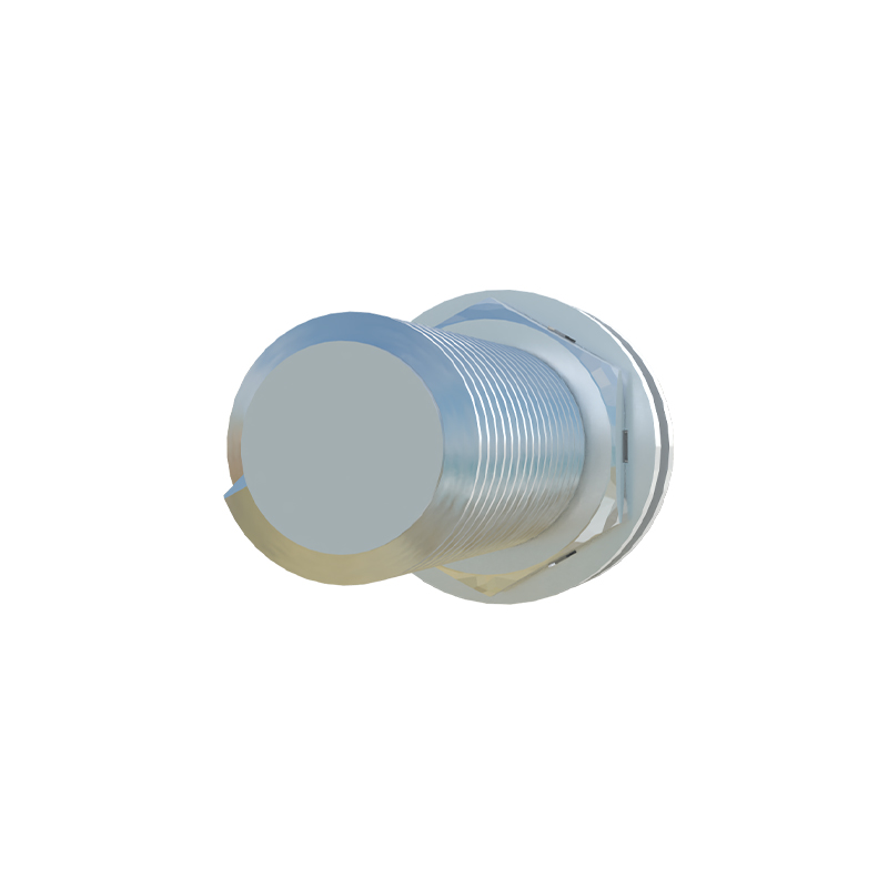
Key Components and Internal Architecture
A standard capacitive proximity switch comprises several critical components. The sensing electrode forms the active surface. A high-frequency oscillator generates the measuring field. The demodulator converts the AC signal from the oscillator into a DC voltage proportional to the amplitude. A Schmitt trigger provides the switching decision with hysteresis to prevent output chatter. Finally, the output stage, which can be NPN, PNP, or analog (4-20mA, 0-10V), provides the interface to the control system. Many models feature a potentiometer for sensitivity adjustment, allowing fine-tuning to ignore certain materials or background objects, a crucial feature for challenging applications.
Primary Advantages Over Other Technologies
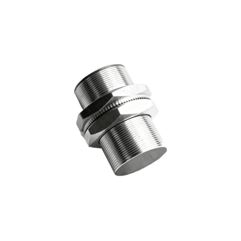
The most significant advantage of capacitive sensors is their material versatility. They can detect virtually any solid or liquid, making them indispensable in diverse industries. They are excellent for non-contact level detection of liquids or bulk solids through non-metallic container walls, eliminating the need for direct contact with the media. Their ability to sense through certain barriers reduces design complexity. Furthermore, they are generally insensitive to target color, surface finish, or reflectivity, which can plague optical sensors. Modern designs offer robust housing (often in PBT or stainless steel), high switching frequencies, and excellent resistance to dust, moisture, and many chemicals.
Common Industrial Applications
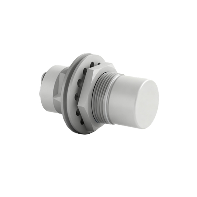
Capacitive proximity switches find widespread use across automation and process control. A classic application is liquid level detection in tanks, whether for high-level prevention or low-level alarm, often sensed through glass or plastic walls. In packaging, they detect the presence of plastic bottles, cardboard boxes, or foil lids. In woodworking and paper processing, they monitor material presence and roll diameter. They are used to control the fill level of powders and granules in silos or hoppers. Additionally, they serve as non-contact pushbuttons in human-machine interfaces, activated by a finger's touch through a glass or plastic panel.
Critical Factors for Sensor Selection
Selecting the right capacitive sensor requires careful consideration of several parameters. First, determine the sensing distance; note that the rated sensing distance is specified for a metal target and reduces for materials with lower dielectric constants. The target material and its dielectric constant directly influence the effective range. The housing style (cylindrical, rectangular, block) must suit the mounting constraints. Output type (NO/NC, NPN/PNP) must match the PLC or controller input card. Environmental conditions like temperature extremes, washdown requirements (IP67/IP69K), or exposure to aggressive chemicals dictate the housing material and ingress protection rating. Always consult manufacturer datasheets for specific performance curves.
Installation and Calibration Best Practices
Proper installation is key to reliable operation. Maintain the recommended clearance around the sensor face to prevent false triggering from the surrounding mounting material (typically 1-2 times the sensor diameter). For level sensing through a container wall, ensure the sensor is mounted flush against the outer surface. During calibration, use the sensitivity potentiometer. Power the sensor and present the actual target material at the desired detection point. Adjust the sensitivity until the output reliably switches, then back it off slightly to provide a safety margin against environmental drift. Avoid sensing metallic backgrounds or large grounded objects in the near field, as they can saturate the sensor's field.
Troubleshooting Typical Issues
Common problems include unstable switching or failure to detect. This is often due to improper sensitivity setting—recalibrate with the actual target. False triggering can be caused by material buildup on the sensor face, condensation, or interference from adjacent moving machinery. Ensure the sensor body is properly grounded according to instructions. For sensing through containers, verify that the wall material and thickness are within the sensor's penetration capabilities. If the sensor outputs continuously, check for a short circuit or that the target is not permanently within the sensing field. Always verify power supply voltage and polarity.
Future Trends and Innovations
The evolution of capacitive sensing