Understanding Motee Photoelectric Sensor Basics
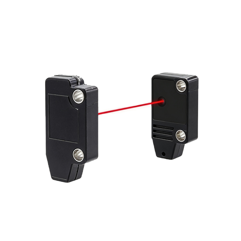
Motee photoelectric sensors are widely used in industrial automation for detecting the presence, absence, or distance of objects without physical contact. These sensors operate by emitting a beam of light (visible red, infrared, or laser) and detecting changes in the received light signal. Before proceeding with wiring, it is crucial to identify your specific sensor model and its type—diffuse, retro-reflective, or through-beam—as this can influence the electrical characteristics. The core components for wiring are the power supply terminals, the output switching element (typically an NPN or PNP transistor), and the load device, such as a programmable logic controller (PLC) input or a relay. Always consult the official datasheet for your specific model for voltage ratings, current limits, and terminal designations, as they are the definitive source of information.
Essential Tools and Safety Precautions
Prior to any electrical work, ensure you have the correct tools: appropriate wire strippers, screwdrivers, a multimeter for verification, and wires of the correct gauge. The most critical step is safety. Disconnect all power sources to the control panel or circuit. Verify that the power is off using a multimeter. Wear appropriate personal protective equipment (PPE). Plan your wiring route to avoid sharp edges, heat sources, or areas with excessive electromagnetic interference. Ensure the sensor's housing is properly mounted and sealed if used in harsh environments. Never exceed the sensor's specified voltage range, as this can cause permanent damage or create a safety hazard.
Wiring a Standard 3-Wire DC Sensor
The majority of Motee photoelectric sensors utilize a 3-wire DC configuration. These wires are typically color-coded: brown for positive supply voltage (+V), blue for common negative (0V or COM), and black for the switched output signal. For an NPN (sinking) output sensor, connect the brown wire to the positive DC supply (e.g., +24VDC). Connect the blue wire to the negative side of the same DC supply (0VDC). The black output wire is connected to the load (e.g., one side of a PLC digital input). The other side of the PLC input is then connected to the positive supply (+24VDC). When the sensor detects an object, the NPN transistor activates, sinking current from the load to the common (blue wire), completing the circuit.
Configuring PNP (Sourcing) Output Sensors
For a PNP (sourcing) output sensor, the power connections remain identical: brown to +V, blue to 0V. The key difference lies in the output function. The black wire from a PNP sensor provides a positive voltage signal when active. Therefore, connect the black output wire to your load (e.g., the PLC input). The other side of the PLC input must now be connected to the common negative (0VDC). When the sensor activates, the PNP transistor sources current from the positive supply, through the sensor's output (black wire), into the load, and back to the common (blue wire). It is vital to match the sensor's output type (NPN/PNP) with the input configuration of your controller to avoid malfunction.
Connecting to a PLC or Control System
Integration with a Programmable Logic Controller is a common application. First, identify whether your PLC input card is designed for sinking (accepts a positive voltage) or sourcing (accepts a connection to common) currents. An NPN sensor works seamlessly with a sinking PLC input. A PNP sensor pairs with a sourcing PLC input. For a typical sinking input card, wire the sensor's black (NPN) output to the PLC input terminal. Connect the PLC input's common terminal to +24VDC. This creates the path described earlier. Always include a protective fuse or circuit breaker in the power supply line to the sensor, and consider using shielded cable for long runs in electrically noisy environments, grounding the shield at one end only.
Troubleshooting Common Wiring Issues
If the sensor fails to operate after wiring, follow a logical troubleshooting sequence. First, re-check all connections against the wiring diagram. Use a multimeter to confirm power is present between the brown and blue wires at the correct voltage. Next, check the output. With the sensor activated (e.g., an object present), measure the voltage between the black and blue wires. For an NPN sensor, it should be near 0V when active; for a PNP, it should be near the supply voltage. If no output signal is present, verify the sensor's detection state using its built-in indicator LED. Ensure the load is not drawing more current than the sensor's rated switching capacity. Incorrect polarity or short circuits are common causes of failure.
Advanced Considerations and Best Practices
For complex setups, consider using a relay as an intermediary between the sensor and a high-power load. Wire the sensor output to the relay coil, and use the relay's contacts to control the larger load. This protects the sensor's delicate output transistor. For sensors with programmable functions or teach-in capabilities, follow the manufacturer's procedure after power is correctly applied. Maintain neat and organized wiring using cable ducts or ties. Clearly label all wires at both ends. For systems with multiple sensors, use a single, adequately rated power supply with proper distribution to avoid ground loops. Regular maintenance, including lens cleaning and connection checks, ensures long-term reliability and prevents downtime in your automation system.