Understanding MX2S Proximity Sensor Insensitivity
The MX2S series of inductive proximity sensors is widely recognized in industrial automation for its robust design and reliable detection capabilities. However, instances of insensitivity, where the sensor fails to detect a target within its specified sensing range, can significantly disrupt production lines and system reliability. This insensitivity manifests as intermittent detection, complete failure to trigger, or requiring the target to be impractically close. The root causes are seldom due to a single factor but are often a confluence of environmental conditions, mechanical misalignment, electrical issues, or component degradation. A systematic approach to troubleshooting is essential to restore optimal sensor performance and ensure the continuity of automated processes.
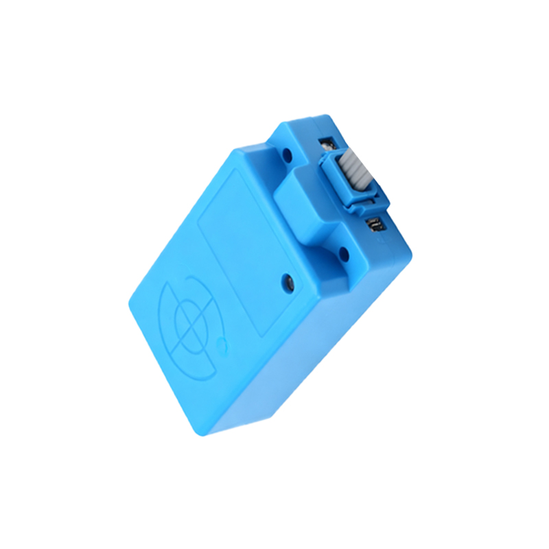
Primary Causes of Detection Failure
Several technical factors can lead to the insensitivity of an MX2S sensor. First and foremost is target compatibility. Inductive sensors like the MX2S are designed to detect ferrous metals. Attempting to sense non-ferrous metals, plastics, or other materials will result in a drastically reduced sensing distance or total failure. Secondly, environmental contamination is a major culprit. The accumulation of metallic dust, chips, or heavy grease on the sensor's active face can create a false "shield," effectively dampening the electromagnetic field and preventing proper target detection. Third, electrical problems such as voltage drops below the sensor's operating range, excessive electromagnetic interference (EMI) from nearby motors or drives, or incorrect wiring can all cause erratic or insensitive behavior.
Mechanical and Installation-Related Factors
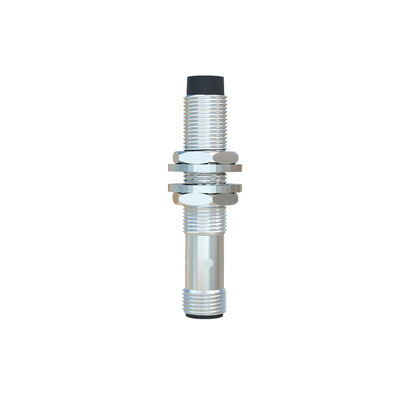
Improper installation is a frequent source of performance issues. The sensor must be mounted securely without undue stress on the housing. Vibration can loosen mounts, gradually changing the alignment between the sensor and the target. Furthermore, the sensing distance is specified for a standard target. If the actual target is smaller than the standard size, the effective sensing distance decreases. Sensor-to-target alignment is also critical; the target should approach the sensor's face perpendicularly for maximum efficiency. An angled approach or excessive lateral offset can lead to missed detections. Finally, physical damage to the sensor face or housing from impacts can compromise internal components.
Step-by-Step Diagnostic Procedure
Begin diagnostics by verifying the basics. Confirm the target material is ferrous steel and meets the sensor's specifications. Clean the sensor's face thoroughly to remove any debris or buildup. Next, check the power supply with a multimeter at the sensor's terminals to ensure it is within the rated voltage range (e.g., 10-30 VDC) under load. Observe the sensor's indicator LED. A steadily illuminated LED when a target is absent may indicate a wiring error or a saturated sensor due to metallic surroundings. A non-illuminated LED during target presentation points to insensitivity. Temporarily replace the sensor with a known-working unit of the same model. If the new sensor operates correctly, the original unit is likely faulty. If the problem persists, the issue lies in the installation or environment.
Environmental Interference and Shielding
The MX2S operates by generating an electromagnetic field. Strong external magnetic fields or high-frequency noise from adjacent equipment can interfere with this field. Ensure the sensor is not installed in close proximity to large transformers, welding equipment, or variable frequency drives (VFDs). If unavoidable, use shielded cables for both power and output signals, and ensure the shield is properly grounded at one end. Maintain adequate clearance between sensors, especially when mounted opposite each other, to prevent mutual interference. In highly corrosive or wet environments, verify the sensor's IP rating is appropriate, as ingress can damage internal circuitry over time.
Corrective Actions and Best Practices
Once the cause is identified, apply the appropriate corrective measure. For installation errors, remount the sensor ensuring correct alignment and a secure fit. Use brackets if necessary to minimize vibration. For electrical issues, stabilize the power supply, add noise filters, or re-route cabling away from sources of EMI. Implement proper cable management and grounding techniques. If the sensor itself is defective, replace it promptly. As a best practice, establish a preventive maintenance schedule that includes regular visual inspections, cleaning of sensor faces, and verification of sensing distances. When specifying sensors, always consider a safety factor by selecting a sensing range 20-30% greater than the application requires to account for wear and environmental variables.
When to Consider Sensor Replacement
Despite their durability, MX2S sensors have a finite operational lifespan. Persistent insensitivity that cannot be resolved through troubleshooting, cleaning, or electrical