Understanding the Through-Beam Photoelectric Sensor Principle
Through-beam photoelectric sensors, also known as opposed-mode sensors, consist of two separate units: a transmitter and a receiver. The transmitter emits a continuous beam of light, typically infrared or laser, which is aimed directly at the receiver. The receiver detects this light beam. An object is sensed when it passes between the two units, interrupting the light path. This fundamental principle makes them highly reliable for detection over long ranges and in challenging environments with dust or dirt, as only a significant reduction in received light intensity triggers the output. The key to rapid adjustment lies in precise alignment of this optical axis between the transmitter and receiver.
Pre-Installation Planning and Preparation
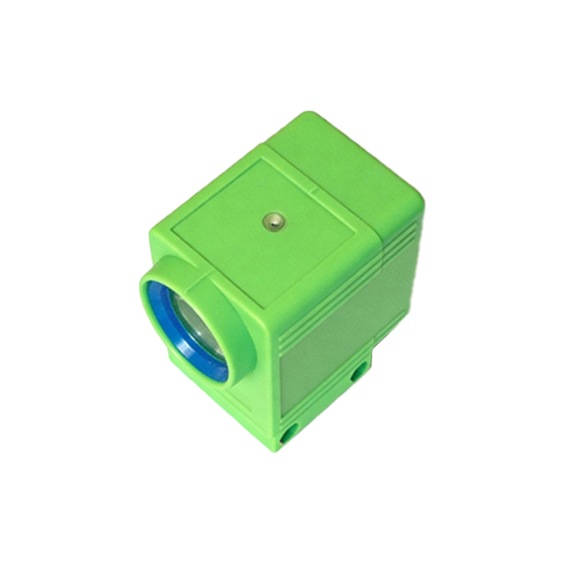
Before mounting the sensors, thorough planning is essential for quick setup. First, determine the required sensing distance and ensure the selected sensor model's specifications exceed this distance by at least 20-30% to account for potential alignment drift or environmental factors like airborne particles. Second, identify a stable mounting surface for both the emitter and receiver. Vibration or movement of the mounting surface will necessitate frequent re-adjustment. Use sturdy brackets designed for the specific sensor housing. Finally, ensure the electrical connections are planned and that power is available at both mounting locations. Having a clear plan prevents time-consuming rework after installation.
Initial Rough Alignment Procedure
Begin by mounting the transmitter and receiver units on their respective brackets, but do not fully tighten the mounting screws; leave them slightly loose to allow for adjustment. Many through-beam sensors feature built-in alignment aids. Turn on the power to both units. Most receivers have a visual indicator, such as a green LED, that illuminates when sufficient light is received. Manually point the transmitter in the general direction of the receiver. Observe the receiver's indicator. The goal in this stage is to get the indicator to turn on, signifying that the beam is hitting the receiver's detection element, even if not perfectly centered.
Fine-Tuning for Maximum Signal Strength
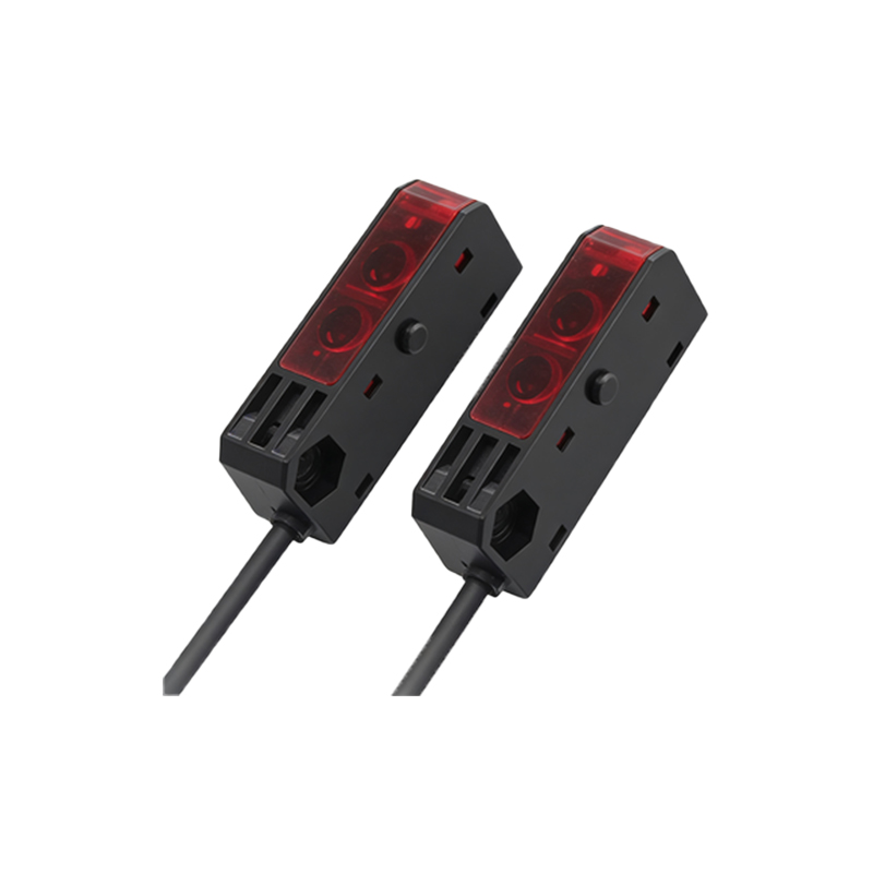
Once the rough alignment is achieved and the receiver's "power-on" or "beam-received" indicator is stable, proceed to fine-tuning. This step is crucial for long-term stability. If the sensor model includes a signal strength indicator (often a series of LEDs or a bargraph display), use it. Carefully adjust the angular position of both the transmitter and receiver in small increments, following the manufacturer's instructions to maximize the indicated signal strength. If no strength indicator is present, tighten the mounting screws gradually while observing the basic reception LED, ensuring it remains steadily lit. The objective is to center the beam on the receiver's active area for the strongest possible signal.
Utilizing Alignment Tools and Features
Leverage any specialized tools provided by the sensor manufacturer to expedite adjustment. Some high-end sensors come with a portable alignment tool or a "teach-in" function that simplifies setup. Laser-emitting models are inherently easier to align visually. For standard infrared sensors, a simple but effective tool is a piece of paper or a small card. Hold it in front of the receiver and move it around; the point where the receiver's indicator turns off most sensitively indicates the center of the beam's path, helping you visualize the alignment. Additionally, some brackets have fine-threaded adjustment screws for precise angular control—use them for the final micro-adjustments.
Securing the Installation and Testing
After achieving optimal alignment, securely tighten all mounting screws. Use a lock washer or thread-locking compound if the environment is prone to vibration. It is critical to tighten the screws in a cross-pattern to avoid shifting the sensor's position. Once secured, perform a rigorous test. Pass the target object through the sensing beam multiple times at different speeds and positions within the detection zone. Verify the sensor's output triggers consistently every time without false triggers. Also, test for environmental robustness by simulating conditions like minor ambient light changes or introducing light dust near the optics.
Troubleshooting Common Alignment Issues
If the sensor fails to align or shows an unstable signal, methodically troubleshoot. First, verify the power supply voltage is within specification at both units. Second, check for physical obstructions in the beam path. Third, ensure the lens surfaces are clean. Fourth, confirm that the transmitter and receiver are from the same model series and are compatible; mixing different types can cause failure. If the beam seems to "drift," re-check the mounting surface stability and ensure brackets are rigid. For long-range applications, consider using sensors with a visible laser beam or a telescopic sight for initial coarse alignment.
Best Practices for Long-Term Stability
To minimize the need for future re-adjustment, adhere to several best practices. Choose sensors with a generous excess gain specification for your application, providing a buffer against lens contamination. Install protective shrouds or hoods to shield the lenses from direct spillage, dust, and mechanical damage. Implement a regular preventive maintenance schedule to clean the lenses with appropriate materials. Periodically, perhaps during scheduled machine downtime, verify the alignment and signal strength. Document the initial signal strength value after installation; a significant drop during a future check indicates it's time for cleaning or re-alignment before a failure occurs.