Understanding Photoelectric Sensor Core Circuit Components
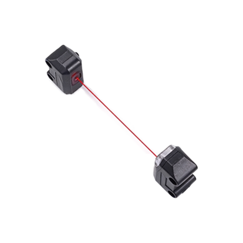
Photoelectric sensors are vital components in industrial automation, relying on a core circuit to transmit and receive light signals for object detection. The core circuit typically consists of an emitter (usually an LED or laser diode), a receiver (phototransistor or photodiode), and associated signal processing circuitry. Before initiating a replacement, it is crucial to identify the sensor model and obtain the correct replacement core or circuit board. Consult the manufacturer's datasheet to understand the specific electrical characteristics, pin configurations, and housing design. Common failure points include degraded emitter output, receiver sensitivity loss, or damage to the amplifier IC. A systematic approach ensures the replacement restores optimal performance without causing further damage to the sensor housing or connected systems.
Essential Tools and Safety Precautions
Gather all necessary tools prior to starting the replacement procedure. You will typically need a set of precision screwdrivers (Phillips and flat-head), needle-nose pliers, a soldering iron with a fine tip, high-quality solder and desoldering braid or a suction pump, anti-static wrist straps, and a multimeter for continuity and voltage testing. Always disconnect the sensor from its power source and lock out/tag out (LOTO) the circuit to prevent accidental energization. Work on a clean, static-free surface. Wear an anti-static wrist strap connected to a proper ground point to prevent electrostatic discharge (ESD) damage to sensitive semiconductor components within the circuit. Ensure adequate lighting and magnification if working with small surface-mount devices.
Step-by-Step Core Circuit Removal Process
Begin by carefully removing the sensor from its mounting bracket if necessary. Locate and remove the housing screws or clips that secure the sensor's enclosure. Gently separate the housing halves, taking note of any sealing gaskets or O-rings for reassembly. Identify the core circuit board, which is often a small PCB connected to the emitter and receiver lenses. Document or photograph the original wiring connections and component orientation. If the core is socketed, gently release any locking tabs and extract the board. For soldered connections, use the soldering iron and desoldering tools to cleanly remove solder from each pin. Apply heat to one pin at a time while gently lifting the board with pliers. Avoid excessive force to prevent damaging the PCB traces or the sensor housing.
Installing and Soldering the New Core Circuit
Position the new core circuit board precisely in its original location within the housing. Ensure the emitter and receiver lenses are correctly aligned with their respective optical ports in the sensor casing. For socketed types, press the board firmly into place until the locking mechanism engages. For soldered types, insert the board's pins or terminals through the corresponding holes in the main PCB or connector block. Apply a small amount of fresh solder to each joint. Use a clean, hot iron to create smooth, concave fillets of solder without bridges between adjacent pins. Avoid prolonged heat application to prevent damaging the new components. After soldering, visually inspect all joints for cold solder joints or shorts. Use a multimeter in continuity mode to verify there are no unintended connections between pins.
Post-Replacement Testing and Calibration
Before reassembling the housing completely, perform a preliminary electrical test. Reconnect the sensor to its power supply according to the wiring diagram, but do not yet mount it. Observe the sensor's indicator LEDs (if present) for normal operation. Use the multimeter to check output signal voltage in both sensing and non-sensing states. For a basic test, pass an object through the sensing field and verify the output switches states correctly. For more advanced sensors, especially those with adjustable sensitivity or timing functions, refer to the manual for recalibration procedures. This may involve adjusting potentiometers on the new core circuit or using a teach-in function. Ensure the sensing range and response time meet the application requirements. Finally, seal the housing properly, reinstalling any gaskets to maintain the sensor's ingress protection (IP) rating. Conduct a final operational test in the actual installed environment.
Troubleshooting Common Post-Replacement Issues
If the sensor fails to operate after replacement, methodically check several key areas. First, verify all wiring connections are correct and secure. Incorrect polarity is a common mistake. Second, inspect for solder bridges or cold solder joints on the new core circuit. Reflow any suspicious connections. Third, confirm the alignment of the optical components; even slight misalignment can drastically reduce sensing range. Fourth, check the power supply voltage with the sensor connected to ensure it is within the specified range. A weak power supply can cause erratic behavior. If the sensor has a modulated light source, ensure the new core's modulation frequency is compatible with the existing system controller. Consult the manufacturer's technical support if persistent issues arise, as the replacement core may be defective or incompatible.