Introduction to Four-Wire Electromagnetic Proximity Sensors
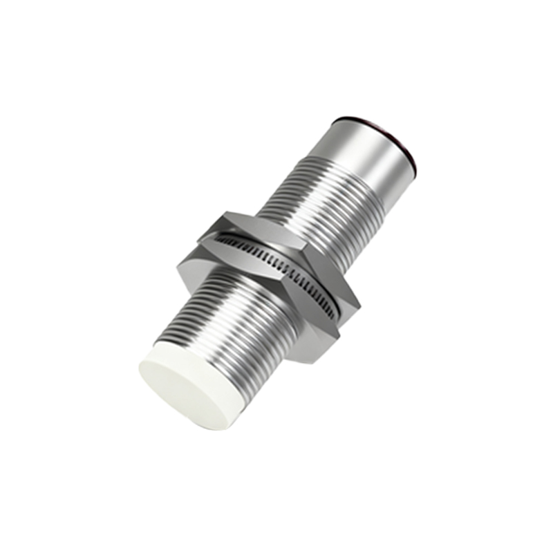
A four-wire electromagnetic proximity switch sensor represents a sophisticated class of non-contact detection devices widely utilized in industrial automation. Unlike simpler two-wire variants, these sensors incorporate four distinct electrical connections, enabling enhanced functionality and reliability. They operate on the fundamental principle of electromagnetic induction, generating an oscillating electromagnetic field from a coil within the sensing head. When a metallic target, typically ferrous, enters this active field, eddy currents are induced on the target's surface. This interaction dampens the oscillation amplitude within the sensor's internal LC tank circuit. The sensor's electronic circuitry detects this change and triggers a solid-state switching output. The four-wire configuration typically includes two wires for the power supply (often DC voltage like 10-30V DC) and two separate wires for the output signal—one for the switched output and a common return. This separation of power and signal paths is a key differentiator, offering significant advantages in system design and diagnostics.
Core Advantages and Functional Benefits
The primary advantage of the four-wire design lies in its electrically isolated output. The switching output is completely separated from the sensor's supply circuit. This isolation provides superior noise immunity, making these sensors exceptionally robust in electrically noisy industrial environments with heavy machinery, variable frequency drives, or welding equipment. It also allows for flexible output configurations; common outputs include NPN (sinking) or PNP (sourcing) transistor types, and sometimes even analog or IO-Link compatible versions for advanced data communication. Furthermore, the dedicated output wires enable the connection of a status indicator LED directly across the output switch, providing clear visual confirmation of the sensor's state independent of the load. This feature is invaluable for troubleshooting and maintenance, allowing technicians to quickly determine if a fault lies with the sensor, the wiring, or the controlled load (e.g., a PLC input or relay coil).
Typical Applications in Industrial Settings
Four-wire electromagnetic proximity sensors are the workhorses of modern manufacturing and process control. Their robustness and accuracy make them ideal for position detection, end-of-travel limit sensing, and object counting in high-speed automation. Common applications include detecting the presence or absence of metal parts on conveyor lines, verifying the closed position of machine guards or valves, and monitoring the position of robotic arms or linear actuators. In metalworking industries, such as stamping or CNC machining, they are used for precise tool positioning and part ejection verification. Their ability to detect only metallic objects, ignoring plastics, wood, or liquids, is a critical feature in material handling and sorting systems. The sealed, often stainless-steel or nickel-plated brass housings, along with high ingress protection (IP) ratings like IP67 or IP69K, allow reliable operation in harsh conditions involving coolants, oils, dust, and high-pressure washdowns.
Key Selection Criteria for Engineers
Selecting the appropriate four-wire sensor requires careful consideration of several technical parameters. First, the sensing distance, or nominal range, must be chosen based on the application's mechanical constraints; it is typically a fraction of an inch to several inches. Engineers must also specify the target material (steel, aluminum, brass, etc.), as the effective sensing range varies with material type and target size. The supply voltage range (e.g., 12-24V DC) must match the available plant voltage. The output type (NPN or PNP) must be compatible with the controller's input module. Physical characteristics are equally important: the housing style (threaded barrel, rectangular, or block-style), connection type (pre-wired cable or quick-disconnect M12 connector), and environmental ratings (temperature range, IP rating, chemical resistance). For demanding safety applications, sensors with built-in diagnostics or designed to meet SIL (Safety Integrity Level) or PL (Performance Level) standards may be required.
Installation, Wiring, and Maintenance Best Practices
Correct installation is paramount for optimal performance. Sensors should be mounted securely to prevent vibration-induced failure or sensing distance variation. A critical rule is to maintain adequate clearance between adjacent sensors and between the sensor and any surrounding metal structure (the "mounting flush" condition) to prevent mutual interference or false triggering. Wiring must follow the manufacturer's diagram precisely: brown wire to DC+, blue wire to DC-, black wire as the switched output, and white wire as the common or second output. Shielding the cable and grounding the shield at the controller end is recommended for long cable runs in noisy environments. Routine maintenance primarily involves keeping the sensing face clean from debris, metal chips, or buildup that could attenuate the electromagnetic field. Periodic functional checks with a