Understanding the E3JK Photoelectric Sensor
The E3JK series represents a versatile line of photoelectric sensors widely used in industrial automation for object detection, counting, and positioning. These sensors operate by emitting a beam of light (typically infrared, red, or laser) and detecting its reflection or interruption. The key to their reliable performance lies in correct electrical installation. Before beginning any wiring procedure, it is crucial to consult the specific datasheet for your E3JK model, as terminal designations and voltage ranges may vary between diffuse-reflective, retro-reflective, and through-beam types. Always ensure the power is disconnected during installation to prevent electrical shock or damage to the sensor.
Identifying Sensor Terminals and Specifications
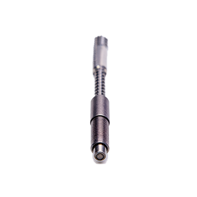
A standard E3JK sensor housing features a terminal block or flying lead wires. Common terminal designations include: Brown wire or terminal for the positive DC supply voltage (typically 10-30 VDC), Blue wire or terminal for the DC common or 0V, and Black wire or terminal for the output signal. Some models may include a White wire for a second output or control function. The output type is critical; models are available with NPN (sinking) or PNP (sourcing) transistor outputs. An NPN output switches the load to common (0V), while a PNP output switches the load to the positive supply. Verify your sensor's output configuration against the requirements of your programmable logic controller (PLC) or relay input to ensure compatibility.
Wiring a DC-Powered E3JK Sensor
For a basic two-wire DC load connection, follow these steps. First, connect the Blue wire to the 0V DC terminal of your power supply. Second, connect the Brown wire to the positive terminal of your DC power supply, ensuring the voltage matches the sensor's rated range (e.g., 12-24 VDC). Third, connect the sensor's output (Black wire) to one terminal of your load device, such as a PLC input or relay coil. Finally, connect the other terminal of the load device back to the power supply. For an NPN sensor, the load connects to the positive supply; for a PNP sensor, the load connects to the 0V common. Always use shielded cable for longer runs to minimize electrical noise interference and secure all connections firmly.
Connecting to a PLC or Control System
Integrating an E3JK sensor with a PLC is a common application. For a DC input module, identify whether the PLC input is designed for Sinking (PNP sensor) or Sourcing (NPN sensor) signals. For example, to connect an NPN E3JK sensor to a sinking PLC input: wire the sensor's Brown lead to +24VDC, the Blue lead to 0VDC, and the Black output lead to the PLC's input terminal. The PLC input's common is internally connected to +24VDC, completing the circuit when the sensor activates. Conversely, for a PNP sensor and a sourcing PLC input, the Black output wire connects to the PLC input, and the input common connects to 0VDC. Always install a protective fuse (typically 1-3A) in the positive supply line close to the power source.
Testing and Troubleshooting the Installation
After wiring, apply power and perform a functional test. Most E3JK sensors have a built-in LED indicator that shows power status and output activation. Pass an object through the sensing field; the output LED should illuminate, and the load should respond. If the sensor fails to operate, first re-check all wiring connections against the diagram. Use a multimeter to verify voltage at the sensor terminals. Ensure the sensing object is within the specified size, distance, and reflectivity parameters. Environmental factors like dust, moisture, or strong ambient light can also affect performance; consider using sensors with specific environmental ratings or protective housings if needed. For persistent issues, consult the manufacturer's troubleshooting guide.
Best Practices for Safe and Reliable Operation
To ensure long-term reliability, adhere to industrial wiring standards. Use the correct wire gauge for the current draw; 18-22 AWG is typical for sensor circuits. Route sensor cables away from high-voltage power lines and motor drives to prevent electromagnetic interference. Employ cable glands or conduits in harsh environments to protect against physical damage and liquids. Implement a regular maintenance schedule to clean the sensor lens and check for loose connections. Properly wiring your E3JK photoelectric sensor not only guarantees immediate functionality but also contributes to the overall safety and efficiency of your automated system, minimizing downtime and maintenance costs.