Introduction to 3-Wire Proximity Sensors
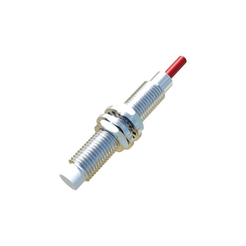
In industrial automation and control systems, proximity switches are indispensable components for non-contact detection of metallic or other objects. Among the various configurations, the 3-wire sensor is the most prevalent and versatile design. This type of sensor integrates the switching element and power supply circuitry into a single, compact housing, requiring three distinct wires for operation: typically brown for positive supply, blue for negative/common, and black for the output signal. Understanding the correct wiring diagram is not merely an installation step; it is fundamental to ensuring system reliability, safety, and optimal performance. Incorrect wiring can lead to sensor failure, damage to connected controllers like PLCs, or unsafe machine operation. This article provides a detailed, professional breakdown of the standard wiring configurations for 3-wire DC proximity sensors, covering both NPN and PNP sourcing types, and their integration into typical control circuits.
Standard Wire Color Coding and Functions
International standards, particularly IEC 60947-5-2, have established common color codes for the leads of 3-wire DC proximity sensors to ensure consistency and reduce wiring errors globally. The brown wire is universally designated for the positive supply voltage (V+ or L+). This wire must be connected to the positive terminal of the DC power source, which commonly ranges from 10 to 30 VDC. The blue wire is designated for the negative or common return (0V or DC Common). This wire connects to the negative terminal of the power supply, completing the sensor's internal circuit. The third wire, which carries the switching output signal, is most frequently black. However, it can sometimes be white or another color, so consulting the specific sensor's datasheet is always mandatory. The function of this output wire—whether it switches the positive voltage (PNP) or the negative path (NPN)—defines the sensor's type and its subsequent wiring to the load.
PNP (Sourcing) Sensor Wiring Configuration
A PNP-type 3-wire proximity sensor is characterized as a "sourcing" device. In this configuration, the internal solid-state switch is connected between the positive supply (brown wire) and the output signal (black wire). When the sensor is inactive (no target detected), the output switch is open, and the black wire is effectively disconnected. Upon detecting a valid target within its sensing range, the internal switch closes. This action connects the black output wire directly to the positive supply voltage from the brown wire. Consequently, the sensor "sources" or provides a positive voltage signal to the load. The typical wiring diagram involves connecting the brown wire to V+, the blue wire to 0V, and the black output wire to one terminal of the load (e.g., a PLC digital input). The other terminal of the load is then connected to the 0V (common) of the power supply. This configuration is predominant in European and many global markets.
NPN (Sinking) Sensor Wiring Configuration
Conversely, an NPN-type 3-wire sensor operates as a "sinking" device. Here, the internal switch is connected between the output signal (black wire) and the negative/common supply (blue wire). When inactive, the output switch is open. When activated by a target, the switch closes, connecting the black output wire to the 0V potential of the blue wire. In this state, the sensor acts as a path to ground or common for the load. The standard wiring diagram requires connecting the brown wire to V+ and the blue wire to 0V, as usual. The black output wire is connected to one terminal of the load. However, the critical difference is that the other terminal of the load must be connected to the positive supply voltage (V+). Thus, when the sensor activates, it completes the circuit by "sinking" current from the load down to 0V. This configuration is historically common in North America and Japan.
Connecting to a Programmable Logic Controller (PLC)
Integrating a 3-wire sensor with a PLC's digital input module is a routine task that demands attention to the input card's design. Most modern PLC input cards are designed as "sinking" or "sourcing" themselves, which must be matched with the complementary sensor type. For a "sourcing" input card (where the internal circuit provides V+ to the field device), an NPN (sinking) sensor is required. The sensor's black wire connects to the PLC input point, and the PLC's common for that group of inputs is connected to V+. For a "sinking" input card (where the internal circuit provides a path to common