Introduction to Photoelectric Sensor Fundamentals
Photoelectric sensors are indispensable components in modern industrial automation and smart lighting systems. These devices operate by emitting a light beam, typically from an LED, and detecting changes in the received light intensity. The core principle hinges on the interaction between the emitted light and the target object. When the beam is interrupted, reflected, or refracted by an object, the sensor's receiver detects this change and converts it into an electrical signal. This signal is then processed to trigger a specific action, such as turning a light on or off, activating machinery, or sending data to a control system. The three primary types are through-beam, retro-reflective, and diffuse reflective sensors, each suited for different sensing ranges and environmental conditions. Understanding these fundamentals is crucial for designing effective and reliable lighting control circuits.
Core Components of a Lighting Control Circuit
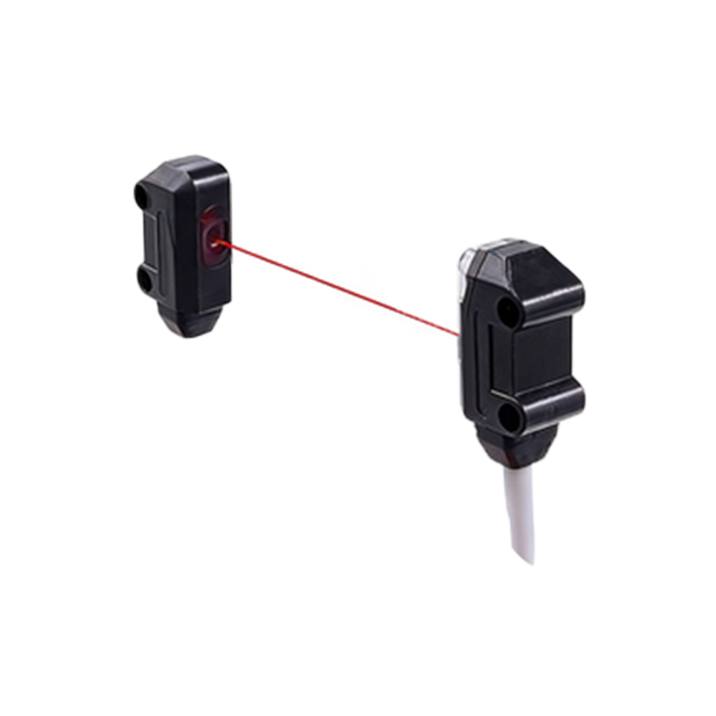
A standard photoelectric sensor lighting control diagram comprises several key interconnected components. At its heart is the photoelectric sensor itself, which includes the emitter and receiver. This is connected to a power supply unit, providing the necessary DC voltage, commonly 12V or 24V DC. The sensor's output is fed into a control relay or a solid-state switching device. For more advanced systems, a Programmable Logic Controller (PLC) acts as the central processing unit, receiving the sensor's signal and executing programmed logic. The final load is the lighting fixture, which could be LED panels, industrial luminaires, or outdoor floodlights. Protective elements like fuses and surge suppressors are also integrated to ensure circuit longevity and safety. The wiring diagram meticulously details the connections between these components, specifying wire gauges, terminal numbers, and grounding points.
Analyzing a Standard Through-Beam Sensor Diagram
A through-beam sensor setup offers the longest sensing range and highest reliability. In its typical lighting control application, the emitter and receiver are housed in separate units placed opposite each other. The wiring diagram shows the emitter connected directly to the power supply. The receiver, upon detecting the uninterrupted light beam, keeps its output transistor in a non-conducting state. When an object interrupts the beam, the receiver's output switches, sending a signal. In a basic relay-based diagram, this signal energizes the coil of a control relay. The relay's contacts, now closed, complete the circuit to the lighting load, turning it on. This diagram clearly labels the normally open (NO) and normally closed (NC) contacts, highlighting the fail-safe design. It's a straightforward "dark-on" operation, where the light turns on when the beam is blocked.
Implementing Retro-Reflective and Diffuse Systems
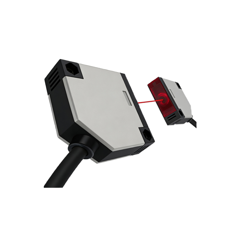
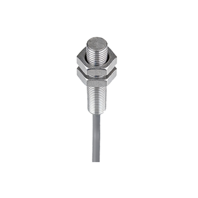
Retro-reflective sensors use a single unit housing both emitter and receiver, along with a reflector. The diagram shows the sensor wired to the power supply, with its output connected to the control input of a lighting contactor. When the beam reflected from the reflector is broken, the output activates. Diffuse reflective sensors, which detect light reflected directly from the target, are commonly used for proximity detection. Their control diagrams often integrate a timer relay. For instance, in a warehouse aisle lighting system, the sensor detects motion and triggers the timer, which keeps the lights on for a preset duration after motion ceases. These diagrams include symbols for the timer's adjustable parameters and show the interlocking wiring to prevent conflicts with other control signals in the facility.
Integration with Programmable Logic Controllers (PLCs)
For complex or scalable lighting control networks, integration with a PLC is standard. The system diagram evolves to include the PLC rack, input/output (I/O) modules, and communication buses. The photoelectric sensor is wired to a discrete DC input module on the PLC. The ladder logic diagram, the software counterpart to the hardware wiring diagram, is where the control logic resides. A simple rung might show the sensor's input address (e.g., I0.0) in series with a timer instruction (TON) to control an output address (Q0.0) linked to the lighting contactor. This allows for sophisticated sequences, such as staggered startup, daylight harvesting based on ambient light sensors, and integration with building management systems via Ethernet/IP or Modbus protocols, all detailed in the network architecture diagram.
Safety and Fail-Safe Design Considerations
Safety is paramount in electrical control diagrams. Photoelectric sensor circuits for lighting, especially in industrial settings, must incorporate fail-safe features. Diagrams explicitly indicate the use of redundant sensors in critical areas to prevent false triggers. Emergency stop circuits are integrated using normally closed contacts that break the control circuit when activated. For sensors with both NO and NC outputs, the diagram specifies which to use to ensure lights turn on during a failure if required for safety (e.g., exit pathways). Proper shielding and grounding symbols are marked to mitigate electromagnetic interference (EMI). Labels for safety extra-low voltage (SELV) circuits powering the sensors are clearly distinguished from the higher-voltage lighting load circuits, adhering to NEC, IEC, or other relevant standards.
Troubleshooting Common Circuit Issues
A practical understanding of the control diagram is essential for troubleshooting. Common issues include no response from the lighting load. The diagram guides the technician to first verify power at the sensor terminals using a multimeter. Next, check if the sensor's indicator LED activates upon beam interruption. If it does, the fault lies downstream—perhaps in the relay coil or the PLC input module. If not, alignment of the through-beam or retro-reflective units must be checked. The diagram helps trace the signal path. Other frequent problems are intermittent operation, often due to loose connections at terminals shown in the diagram, or electrical noise, which necessitates checking the grounding paths and shield connections as illustrated. A systematic approach following the diagram's logic flow is the key to efficient diagnostics.
Advanced Applications and Networked Lighting Control
Beyond simple on/off control, modern diagrams depict advanced systems. These include analog sensors feeding 4-20mA or 0-10V signals to analog input modules to measure light intensity for continuous dimming control. Diagrams for area lighting in smart buildings show multiple sensors networked via IO-Link or wireless protocols to a central gateway, creating a mesh of detection zones. The power-over-ethernet (PoE) diagrams are also emerging, where both data and power for sensor and LED fixtures are delivered over a single Ethernet cable, simplifying installation. These advanced schematics include detailed topology drawings, IP address assignments, and software configuration parameters, representing the convergence of industrial automation and IT networking principles in lighting control.