Understanding Slot Type Photoelectric Sensor Basics
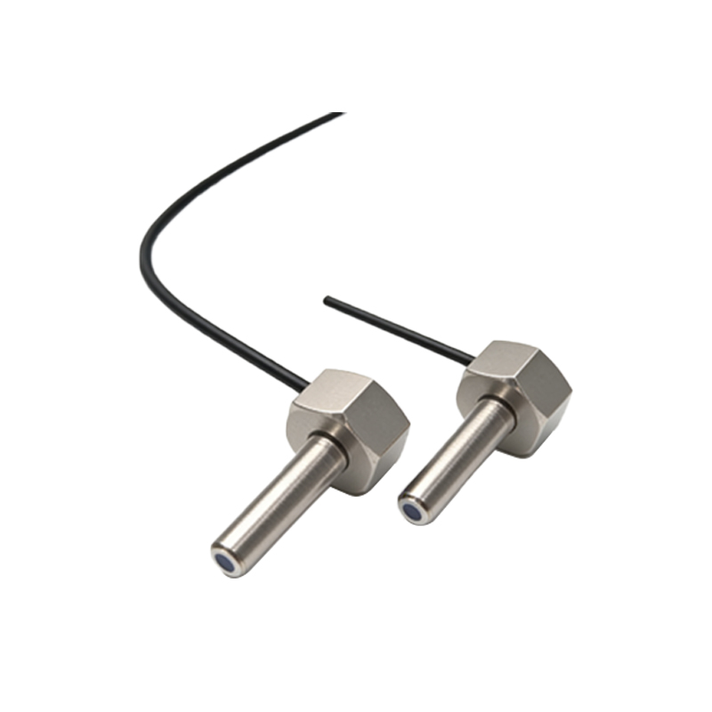
Slot type photoelectric sensors, also known as through-beam sensors, consist of two separate units: an emitter and a receiver. The emitter projects a light beam directly across the gap to the receiver. When an object passes through the slot, it interrupts this beam, causing the sensor's output to change state. These sensors are widely used for object detection, counting, and positioning in automation systems due to their high reliability and precision. Before wiring, it is crucial to identify the sensor model and refer to its datasheet, as specifications like voltage ratings, output types (e.g., NPN or PNP), and connection diagrams can vary significantly between manufacturers.
Pre-Wiring Safety and Preparation Steps
Always disconnect power to the control circuit before beginning any wiring work to prevent electrical shock or damage to the sensor. Gather necessary tools, including wire strippers, screwdrivers, and appropriate cables. Inspect the sensor and its slot for any physical damage or debris that could affect performance. Ensure the operating environment is suitable, considering factors like ambient light, temperature, and potential contaminants. Verify the power supply voltage matches the sensor's requirements, typically ranging from 10-30 VDC for many industrial models. Proper preparation minimizes risks and ensures a smooth installation process.
Identifying Sensor Terminals and Wiring Diagrams
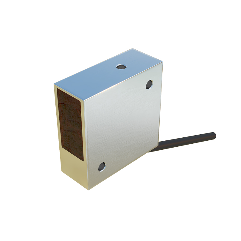
Most slot type photoelectric sensors have three to four terminals, commonly labeled or color-coded. Standard terminals include: brown wire for positive DC supply (+V), blue wire for negative DC supply (0V or common), and black wire for the output signal. Some models may include a white wire for a second output or function. The wiring diagram, usually found on the sensor housing or in its manual, is essential for correct connections. For NPN output sensors (sinking output), the black wire connects to the load, which then connects to positive voltage. For PNP output sensors (sourcing output), the black wire connects to the load, which then connects to ground. Confirming these details prevents reverse polarity or incorrect signal issues.
Step-by-Step Wiring Procedure
First, connect the power wires. Strip the insulation from the power supply cables and attach the brown wire to the positive (+) terminal and the blue wire to the negative (-) terminal on the sensor. Use secure connections, such as terminal blocks or soldering, to avoid loose contacts. Next, handle the output wire. Connect the black output wire from the sensor to the input terminal of your controller, relay, or indicator device. If using a shielded cable for noise reduction, ground the shield at one end only, typically to the earth ground of the power supply. Finally, double-check all connections against the wiring diagram to ensure accuracy before applying power.
Testing and Troubleshooting Common Issues
After wiring, restore power and test the sensor. Pass an object through the slot; the output should activate, often indicated by an LED on the sensor. If the sensor fails to respond, first check the power supply voltage with a multimeter. Verify that the output load is compatible and within the sensor's current rating. Common problems include misalignment of the emitter and receiver, which can be corrected by adjusting their positions until the beam is unobstructed. Environmental interference, such as strong ambient light or dust, may require using a sensor with modulated light or installing protective covers. Consult the manual for specific error indicators or reset procedures.
Best Practices for Installation and Maintenance
To ensure long-term reliability, install the sensor securely using appropriate brackets, avoiding excessive vibration or mechanical stress. Align the emitter and receiver precisely within the slot to maintain optimal beam strength. For applications in harsh conditions, select sensors with suitable IP ratings for dust and water resistance. Regularly clean the lens surfaces with a soft cloth to prevent buildup that could weaken the signal. Periodically inspect wiring for wear or corrosion, especially in dynamic environments. Following these practices enhances sensor lifespan and system performance, reducing downtime in industrial operations.