Understanding Proximity Sensor Fundamentals
Proximity sensors are non-contact electronic devices designed to detect the presence or absence of an object within a specific sensing range. Unlike mechanical limit switches, they operate without physical contact, making them ideal for applications requiring high reliability, fast response times, and minimal wear. The core principle involves generating an electromagnetic field or a beam of radiation (like infrared light) and monitoring changes in the field or the return signal. When a target object enters this field, it causes a detectable alteration—such as a change in oscillation amplitude, capacitance, or light reflection—which the sensor's circuitry converts into a clean electrical output signal. This output typically switches from a high to a low state (or vice-versa), signaling the object's detection to a connected controller like a PLC.
Selecting the Appropriate Sensor Type
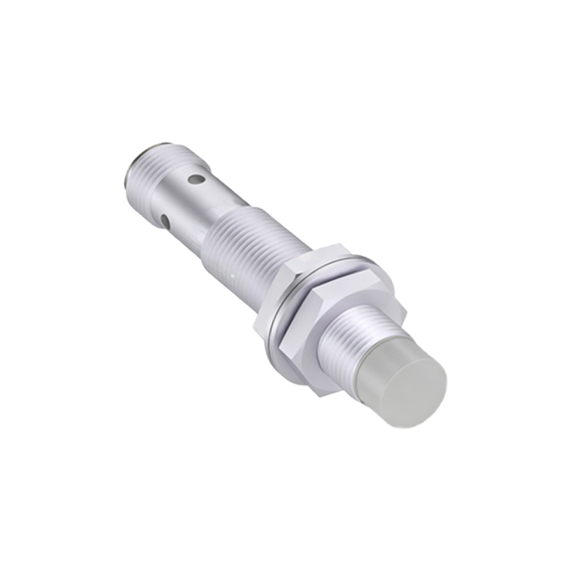
Choosing the right sensor is critical for optimal performance. The main types are inductive, capacitive, ultrasonic, and photoelectric. Inductive sensors detect metallic objects, primarily ferrous metals like steel and iron, but some models can also sense non-ferrous metals like aluminum or copper at reduced ranges. They are robust, immune to environmental factors like dust or oil, and perfect for machine automation. Capacitive sensors can detect nearly any material—metals, plastics, wood, liquids, and granular substances—by sensing changes in capacitance. They are used in level detection or material handling. Ultrasonic sensors use sound waves to detect objects and measure distance, functioning well in challenging environments with dust, smoke, or varying colors. Photoelectric sensors use light beams and are excellent for long-range detection and sensing small or transparent objects. The selection depends on the target material, required sensing distance, environmental conditions, and the needed response speed and output type.
Proper Installation and Mounting Considerations
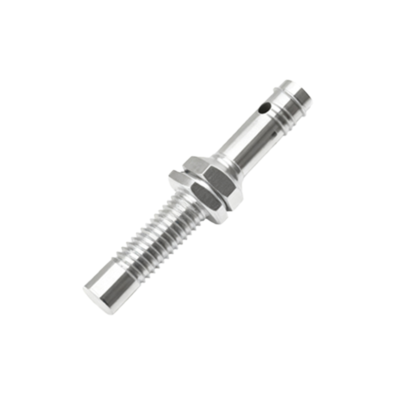
Correct installation is paramount for reliable operation. First, ensure the sensor is mounted securely to prevent vibration-induced false triggers. Maintain the specified sensing distance (Sn) between the sensor's active face and the target. For inductive and capacitive sensors, it's crucial to consider the mounting style—flush-mounted or non-flush. Flush-mounted inductive sensors can be embedded in metal without affecting their range, while non-flush types offer longer ranges but require clearance from surrounding metal. Always provide adequate lateral clearance from other metal objects to avoid interference. For photoelectric and ultrasonic sensors, ensure the sensing path is clear of obstructions and ambient light or sound noise is minimized. The sensor must be aligned correctly with the expected path of the target object. Additionally, consider using mounting brackets or shields to protect the sensor from physical damage or accumulation of debris.
Electrical Wiring and Connection Procedures
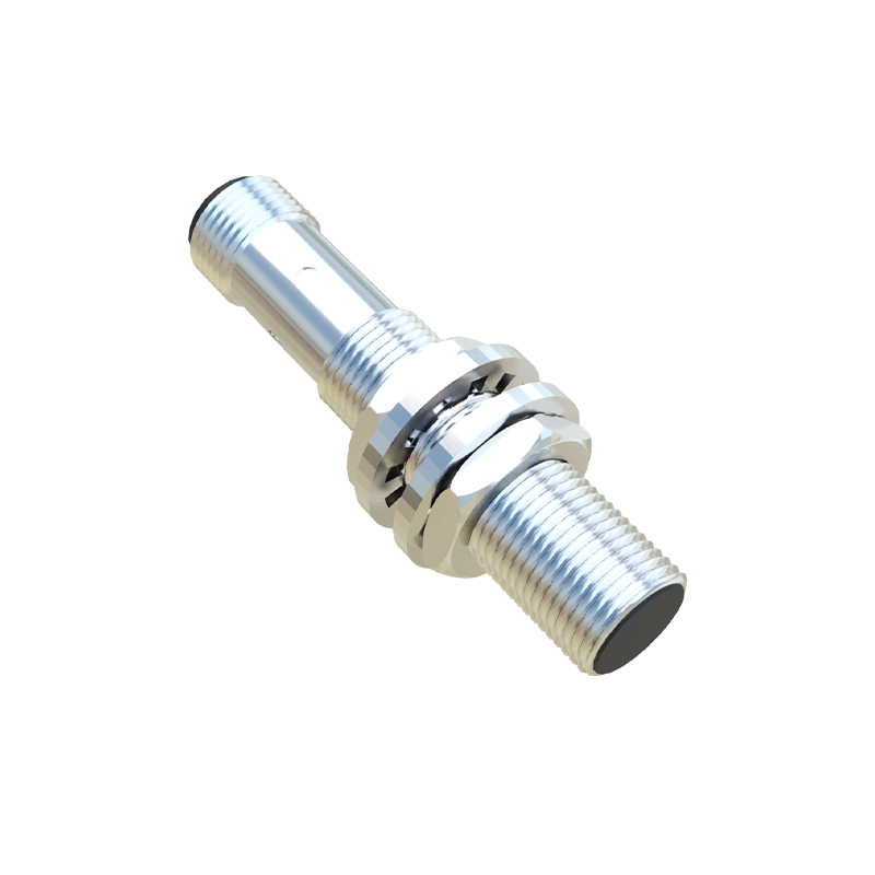
Accurate wiring ensures the sensor integrates seamlessly with your control system. Most industrial proximity sensors have three wires or four wires for DC models: typically brown for DC positive (+V), blue for DC common (0V), and black for the output signal. For AC sensors, two wires carry both power and the switched output. Always consult the manufacturer's datasheet. Key steps include: disconnecting all power sources; routing cables away from high-voltage power lines to prevent electrical noise interference; using conduit or shielded cables in noisy environments; and ensuring proper grounding. Connect the output to the correct input module on your PLC or controller, matching the sensor's output type (NPN sinking or PNP sourcing) to the controller's requirements. Incorrect matching can lead to malfunction. After connections are secure, apply power and observe the sensor's indicator LED (if present) to verify normal standby operation.
Configuring Sensitivity and Setting the Sensing Range
Many proximity sensors feature a potentiometer or teach-in function for adjusting sensitivity. This adjustment is crucial for fine-tuning the sensor to detect specific objects while ignoring background or unwanted targets. For instance, a capacitive sensor detecting a water level in a tank might need adjustment to ignore the tank wall. To configure, introduce a standard target object at the desired detection point and slowly adjust the potentiometer until the output LED just activates. Then, test with non-target conditions to ensure no false triggering. For ultrasonic sensors, you often set a window or threshold for the measured distance. Avoid setting the sensitivity at its maximum, as this can make the sensor unstable and prone to noise. The effective sensing range can be influenced by the target material's size, shape, and composition, so always test under real operating conditions.
Implementing Effective Troubleshooting Practices
Even well-installed sensors can encounter issues. A systematic troubleshooting approach saves time. Begin by checking the indicator LED. A steady LED often indicates power and normal operation, while a blinking pattern may signal an error or overload condition. If the sensor fails to detect, verify: power supply voltage is within specification